GET Cellular Communicator
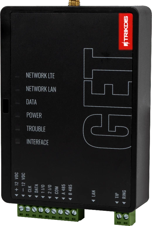
1. Description
The communicator is designed to transmit event messages from the control panel to the CMS (Central Monitoring Station) and the Protegus2 application.
Cellular/Ethernet communicator GET can be directly connected to DSC, Paradox, UTC Interlogix (CADDX), Texecom, Innerrange, Honeywell control panels. The communicator can also be connected to the telephone communicators (which supports the Contact ID communication protocol transmitted by DTMF tones) of control panels.
Communicator transmits full event information to the Central Monitoring Station.
Communicator works with Protegus2 application. With Protegus2 users can control their alarm system remotely and get notifications about security system events. The Protegus2 app works with all security alarm panels from various manufacturers to which the GET communicator is connected. Communicator can transmit event notifications to the Central Monitoring Station and work with Protegus2 simultaneously.
1.1 Features
Connects to the control panel's serial or keyboard bus or telephone line (TIP/RING).
Sends events to monitoring station receiver:
-
Sends events to TRIKDIS software or hardware receivers that work with any monitoring software.
-
Can send event messages to SIA DC-09 receivers.
-
Can send event messages to SUR-GARD receivers. The annex has a table for converting Contact ID codes to SIA codes.
-
Monitoring the connection by sending a PING request to the IP receiver every 30 seconds (or by user defined period).
-
Backup channel, that will be used if connection with the primary channel is lost.
-
With parallel communication channel events can be sent to two receivers at same time.
-
When Protegus2 service is enabled, events are first delivered to CMS, and only then are sent to app users.
Works with Protegus2 app:
-
“Push” and special sound notifications informing about events.
-
Remote system Arm/Disarm.
-
Remote control of connected devices (lights, gates, ventilation systems, heating, sprinklers, etc.).
-
Different user rights for administrator, installer and user.
Notifies users:
- Users can be notified about events with Protegus2 app.
Controllable outputs and inputs:
-
2 double I/O terminals that can be set either as input (IN) or controllable output (OUT) terminals.
-
Outputs controlled by the Protegus2 app.
Quick setup:
-
Settings can be saved to file and quickly written to other communicators.
-
Two access levels for configuring the device for CMS administrator and for installer.
-
Remote configuration and firmware updates.
1.2 List of compatible control panels
| Manufacturer | Model |
|---|---|
| DSC® | PC585, PC1404, PC1565, PC1616, PC1832, PC1864, PC5020 |
| PARADOX® | SPECTRA SP4000, SP5500, SP6000, SP7000, SP65, SP5500+, SP6000+, SP7000+ |
| PARADOX® | MAGELLAN MG5000, MG5050, MG5050E, MG5050+, MG5075 |
| PARADOX® | DIGIPLEX EVO48, EVO192, EVOHD, EVOHD+ |
| PARADOX® | SPECTRA 1727, 1728, 1738 |
| PARADOX® | ESPRIT E55 |
| UTC Interlogix® | NetworX (Caddx) NX-4v2, NX-6v2, NX-8v2, NX-8e |
| Texecom® | Premier 24, 48, 88, 168, 640 / Premier Elite 12, 24, 48, 64, 88, 168, 640 |
| Innerrange® | Inception, Integriti |
| Honeywell® | Ademco Vista-15, Ademco Vista-20, Ademco Vista-48 |
Underlined - Control panels directly controlled by communicator***.*** Firmware PARADOX control panels, which are directly controlled, must be V.4 or higher.
* Connect control panels from other manufacturers to the GET communicator using the TIP RING terminals of the control panel.
1.3 Communicator model types
This manual is for LTE communicators.
1.4 Specifications
| Parameter | Description |
|---|---|
| Network connectivity | LTE / Ethernet |
| Connection to control panel | Serial bus, Keypad bus or TIP RING |
| Dual purpose terminals [IN/OUT] | 2, can be set as either NC; NO; NC/EOL; NO/EOL; NC/DEOL; NO/DEOL (2,2 kΩ) type inputs or open collector (OC) type outputs with current up to 0,15 A, 30 VDC max. |
| Modem EG915U-EU / (Europe) | LTE FDD: B1/B3/B5/B7/B8/B20/B28 |
| Modem EG915U-EU / (Europe) | GSM: B2/B3/B5/B8 |
| Modem EG915U-LA / (Latin America) | LTE FDD: B2/B3/B4/B5/B7/B8/B28/B66 |
| Modem EG915U-LA / (Latin America) | GSM: B2/B3/B5/B8 |
| Modem BG95-M5 (Cat M1) | LTE-FDD: B1/B2/B3/B4/B5/B8/B12/B13/B18/B19/B20/B25/B26/B27/B28/B66/B85 |
| Modem BG95-M5 (Cat M1) | EGPRS: 850/900/1800/1900 MHz |
| Power supply voltage | 10-18 V DC |
| Current consumption | 175 mA |
| Transmission protocols | TRK8, DC-09_2007, DC-09_2012, TL150 |
| Message encryption | AES 128 |
| Buffer memory capacity | 60 events |
| Changing settings | With TrikdisConfig computer program remotely or locally via USB-C port |
| Operating environment | Temperature from -10 °C to 50 °C, relative humidity - up to 80% at +20 °C |
| Communicator dimensions | 113 x 70 x 25 mm |
| Weight | 110 g |
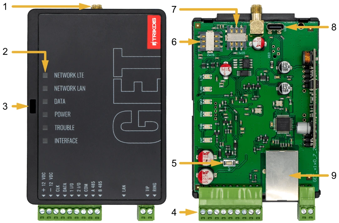
1.5 Communicator elements
-
Cellular antenna SMA connector
-
Light indicators
-
Frontal case opening slot
-
Terminal for external connections
-
“RESET” button.
-
SIM2 card slot
-
SIM1 card slot
-
USB-C port for communicator programming
-
Ethernet connection RJ45 socket
1.6 Purpose of terminals
| Terminal | Description |
|---|---|
| +12 VDC | +10 V/+18 V DC power supply |
| -12 VDC | 0 V DC power supply |
| CLK | Serial bus terminals for direct connection to control panel |
| I/O 1 | 1st input/output terminal (default setting – OUT) |
| I/O 2 | 2nd input/output terminal (default setting – OUT) |
| COM | Common (negative) terminal |
| A 485 | Not used |
| LAN | Ethernet connection RJ45 socket |
| TIP | Terminal to connect with control panel TIP terminal |
| RING | Terminal to connect with control panel RING terminal |
1.7 LED indication of operation
| Indicator | Light status | Description |
|---|---|---|
| NETWORK LTE | Off | No connection to cellular network |
| NETWORK LTE | Yellow blinking | Connecting to cellular network |
| NETWORK LTE | Green solid with yellow blinking | Communicator is connected to cellular network. / Sufficient cellular signal strength for 4G level 3 (three yellow flashes) |
| NETWORK LAN | Off | No connection to a computer network |
| NETWORK LAN | Green solid | Communicator is connected to a computer network |
| DATA | Off | No unsent events |
| DATA | Green solid | Unsent events are stored in buffer |
| DATA | Green blinking | (Configuration mode) Data is being transferred to/from communicator |
| POWER | Off | Power supply is off or disconnected |
| POWER | Green solid | Power supply is on with sufficient voltage |
| POWER | Yellow solid | Power supply voltage is insufficient (≤11.5V) |
| POWER | Green solid and yellow blinking | (Configuration mode) Communicator is ready for configuration |
| POWER | Yellow solid | (Configuration mode) No connection with computer |
| TROUBLE | OFF | No operation problems |
| TROUBLE | 1 red blink | Connection error at the "physical" level (PHY Link status error), check LAN cable |
| TROUBLE | 2 red blinks | SIM1 card error |
| TROUBLE | 3 red blinks | SIM2 card error |
| TROUBLE | 7 red blinks | Lost connection with control panel (serial bus) |
| INTERFACE | - | Not used |
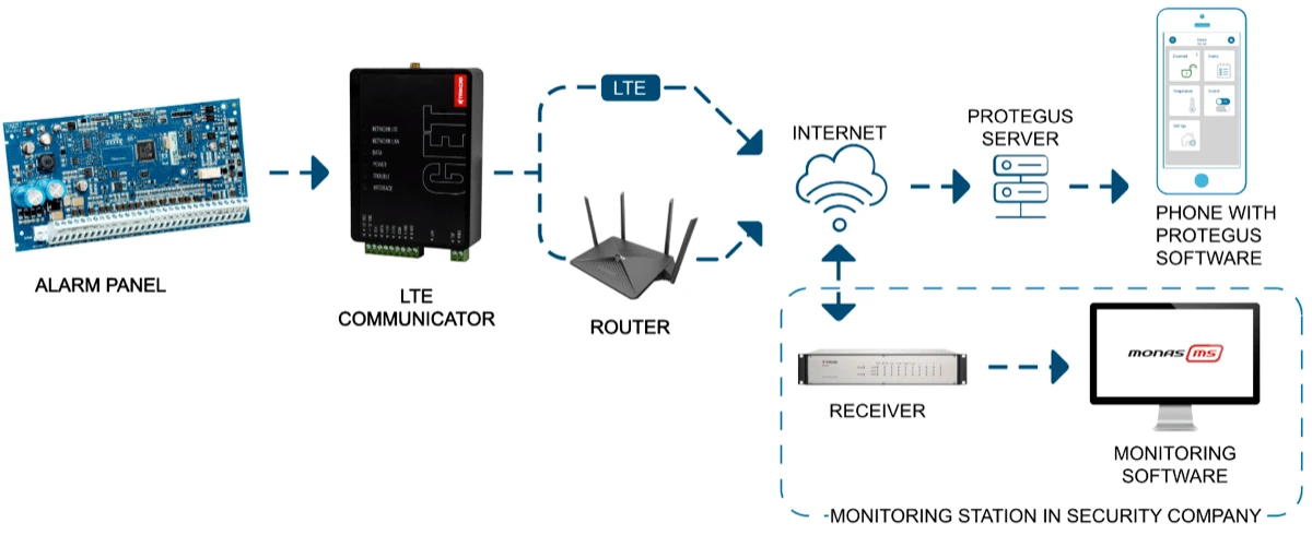
1.8 Structural schematic of using the GET communicator
Note
Before you begin, make sure that you have the necessary:
-
USB-C cable for configuration.
-
At least 4-wire cable for connecting communicator to control panel.
-
CRP2.4 cable for connecting to Paradox panel`s serial port.
-
Flat-head 2,5 mm screwdriver.
-
Sufficient gain cellular antenna if network coverage in the area is poor.
-
Activated SIM card (PIN code request can be turned off).
-
Particular security control panel`s installation manual.
Order the necessary components separately from your local distributor.
2. Quick configuration
Below we describe what settings need to be set for the communicator to begin sending events to the Central Monitoring Station (CMS) and to allow the security system to be controlled with the Protegus2 app.
You can make these settings in the Protegus app or in TrikdisConfig; each section below gives the steps for both.
The communicator must be online and added to your Protegus account (see Adding the security system to Protegus2 app). If it can't connect yet, for example because the SIM card needs a PIN or a different APN, make these settings with TrikdisConfig first.
-
In the Protegus app, open the system and go to Settings → Advanced settings.
-
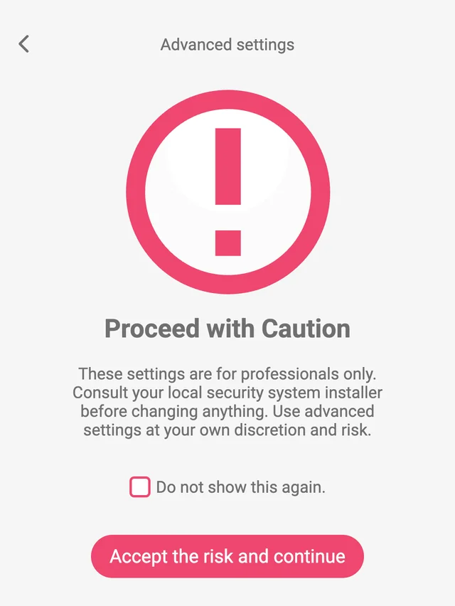
The first time, the app shows Proceed with Caution. Tap Accept the risk and continue. Tick Do not show this again. to skip it next time.
-
The app reads the communicator's settings. If it asks for the Service Access code, enter the communicator's Protegus Cloud access code (default 123456).
-
Change the settings described below, then tap Write to save them to the communicator.
Note
The Protegus app supports GET firmware 1.08 or later.
-
Download TrikdisConfig configuration software from www.trikdis.com (type “TrikdisConfig” in the search field) and install it.
-
Open the casing of the communicator with a flat-head screwdriver as shown below:
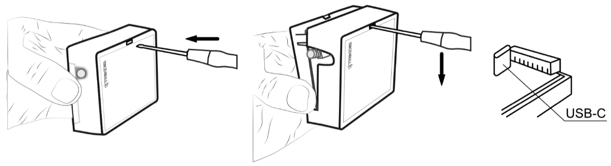
-
Using a USB-C cable connect the communicator to the computer.
-
Run TrikdisConfig. The software will automatically recognize the connected communicator and will open a window for configuration.
-
Click Read [F4] to read the communicator’s settings. If requested, enter the Administrator or Installer 6-digit code in the pop-up window.
2.1 Settings for connection with Protegus2 app
In the Protegus app, open Settings → Advanced settings and set:
-
Panel settings → TLF (communicator connected to the TIP/RING terminals of the control panel): set Security panel model to AUTO.
-
Panel settings → Serial Bus (communicator connected to the keypad bus or serial bus): select the Security panel model.
-
On the same screen, turn on Remote Arm/Disarm if users should control the panel in the Protegus app with their keypad code. This setting is only shown for directly controlled panels.
-
For direct control of Paradox panels, enter the PC download password; for Texecom panels, the UDL passcode. It must match the password entered in the control panel.
-
User reporting → Cloud: turn on Enabled, and change the Cloud access code if users should be asked for it when adding the system to the Protegus app (default 123456).
-
Network settings → LAN (communicator connected to a LAN network): turn on Use DHCP.
-
Network settings → SIM and SIM2 (for each inserted SIM card): enter the SIM card PIN and the APN. Check that DNS1 and DNS2 match those supported by your ISP.
-
Reporting to CMS → CMS settings → Reporting mode: set Main type, Backup type and Backup type 2, the order in which the communicator uses LAN, SIM (SIM1) and SIM2.
-
Tap Write.
Note
For direct panel control to work, you will need to change the panel settings. How to do this is described in chapter 4.1 "Programming of control panels when the communicator is connected to the keypad bus or serial bus".
In TrikdisConfig, set:
In “Panel settings” window:
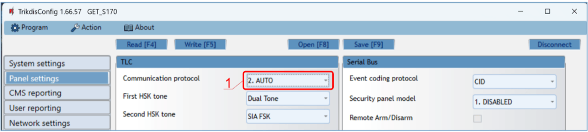
- If the communicator is connected to the TIP/RING terminals of the control panel, then you need to make the “AUTO” setting.
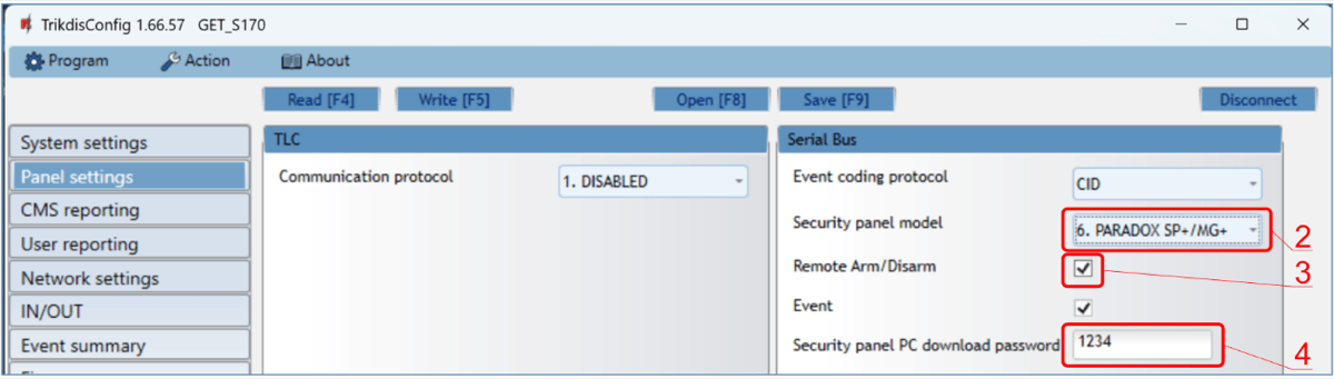
The communicator is connected to the keypad bus or serial bus of the control panel.
-
Select “Security panel model” that will be connected to the communicator.
-
Select “Remote Arm/Disarm” if you want users to be able to control the panel in Protegus2 app with their keypad code. This setting is only shown for directly controlled panels.
-
For the direct control of Paradox and Texecom panels enter “Security panel PC download password”. It must match the password that is entered in the control panel.
Note
For the direct panel control to work, you will need to change the panel settings. How to do this is described in chapter 4.1 "Programming of control panels when the communicator is connected to the keypad bus or serial bus". In this section you will find information on how to change the "PC download/UDL password".
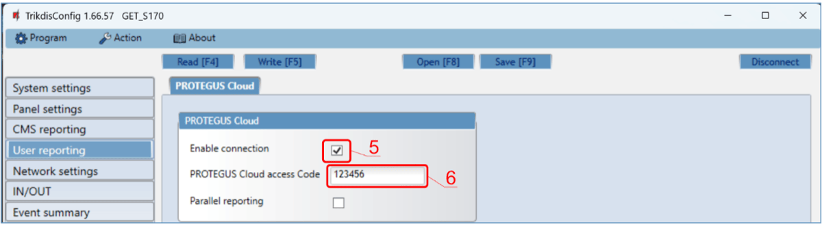
In “User reporting” window, “PROTEGUS Cloud” tab:
-
Tick the checkbox “Enable connection” to the Protegus Cloud.
-
Change the “PROTEGUS Cloud access Code” for logging in to Protegus2 if you want users to be asked to enter it when adding the system to Protegus2 app (default password – 123456).
In “Network settings” window:
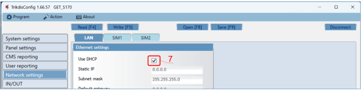
These settings must be made if the communicator is connected to a LAN network.
- Check “Use DHCP” the box so that the communicator automatically reads the computer network settings (subnet mask, gateway) and is assigned an IP address.
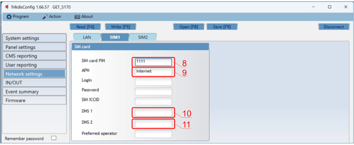
These settings must be made if the SIM (or two SIM cards) card is inserted into the communicator.
-
Enter “SIM card PIN” code.
-
Change “APN” name. “APN” can be found on the website of the SIM card operator (“internet” is universal and works in many operator networks).
-
DNS1, DNS2: Google DNS server is set by default. Regardless of IP settings, make sure the DNS addresses match those supported by your ISP.
In “CMS reporting” window:
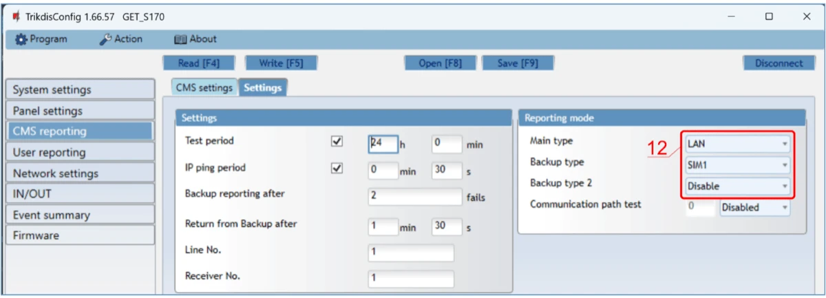
- In the group of options "Reporting mode", the order of communication channels is set, how the communicator will send messages to CMS and to Protegus2. The connection types are specified in order. If the communicator fails to connect using the “Main type” connection , it switches to the “Backup type”, and so on. If the backup connection type was successful in transmitting the message to the CMS, then the Return to main connection type will be attempted after the specified time interval.
After finishing configuration, click the button Write [F5] and disconnect the USB cable.
Note
For a description of all GET settings, see Communicator settings.
2.2 Settings for connection with Central Monitoring Station
In the Protegus app, open Settings → Advanced settings and set:
-
System options → System general: enter the Account No. provided by the Central Monitoring Station (0-9, A-F; do not use FFFE, FFFF). On hardware version x1x1 with firmware 1.31 or later, the account number is set per channel instead: Reporting to CMS → CMS settings → Primary channel → Primary Account no. You can tell from the screen: if System general shows only Time set, use the channel setting.
-
Panel settings → TLF (TIP/RING connection): set Security panel model to AUTO. Or Panel settings → Serial Bus (keypad or serial bus connection): select the Security panel model.
-
Reporting to CMS → CMS settings → Primary channel: turn on Enabled, then set:
- Communication type: IP.
- Domain or IP and Port of the receiver.
- TCP or UDP.
- Protocol: TRK8 (to TRIKDIS receivers), DC-09_2007 or DC-09_2012 (to universal receivers), TL150 (to SUR-GUARD receivers).
- The encryption key that is set in the receiver: TRK encryption key for TRK protocols; for DC-09, turn on Enable encryption key and enter the DC-09 encryption key.
-
(Recommended) Set up the Backup channel the same way.
-
Reporting to CMS → CMS settings → Reporting mode: set Main type, Backup type and Backup type 2.
-
Network settings → LAN (LAN connection): turn on Use DHCP. Network settings → SIM and SIM2 (for each SIM card): enter the SIM card PIN and the APN, and check DNS1 and DNS2.
-
Tap Write.
In TrikdisConfig, set:
In “System settings” window:
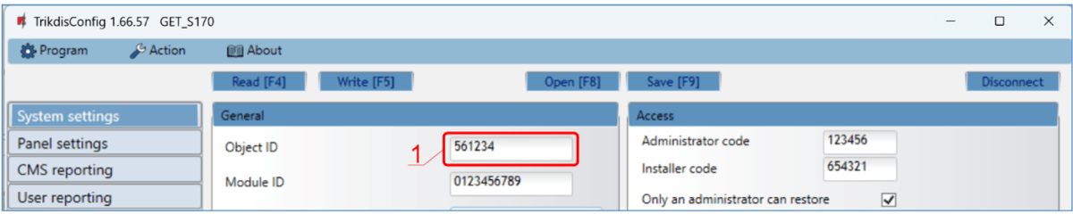
- Enter “Object ID” (account) number provided by the Central Monitoring Station (characters, 0-9, A-F. Do not use FFFE, FFFF Object ID).
In “Panel settings” window:
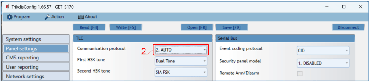
- If the communicator is connected to the TIP/RING terminals of the control panel, then you need to make the “AUTO” setting.
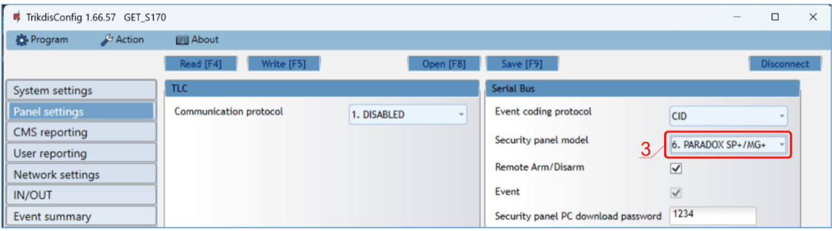
- Select “Security panel model” that will be connected to the communicator.
In “CMS reporting” window settings for “Primary channel”:
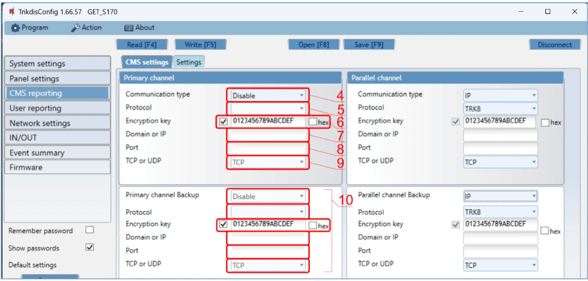
The screenshot shows the window before configuration: the Primary channel is still disabled.
-
Communication type - select the IP connection method.
-
Protocol - select the protocol type for event messages: TRK8 (to TRIKDIS receivers), DC-09_2007 or DC-09_2012 (to universal receivers), TL150 (to SUR-GUARD receivers).
-
Encryption key - enter the encryption key that is set in the receiver.
-
Domain or IP - enter the receiver’s Domain or IP address.
-
Port - enter receiver’s network port number.
-
TCP or UDP - choose event transmission protocol (TCP or UDP) in which events should be sent.
-
(Recommended) Configure “Primary channel Backup” settings.
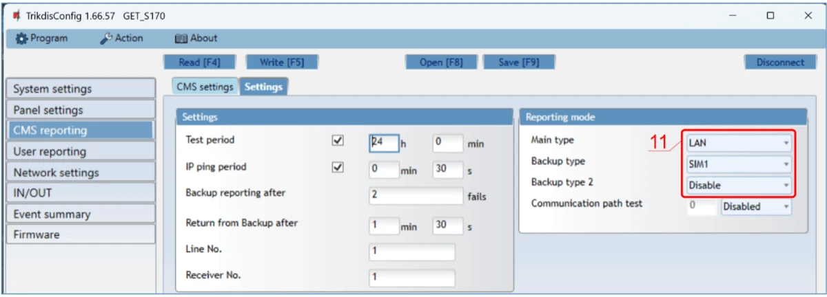
- In the group of options "Reporting mode", the order of communication channels is set, how the communicator will send messages to CMS and to Protegus2. The connection types are specified in order. If the communicator fails to connect using the “Main type” connection , it switches to the “Backup type”, and so on. If the backup connection type was successful in transmitting the message to the CMS, then the return to main connection type will be attempted after the specified time interval.
In “Network settings” window:
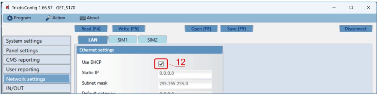
These settings must be made if the communicator is connected to a LAN network.
- Check “Use DHCP” the box so that the communicator automatically reads the computer network settings (subnet mask, gateway) and is assigned an IP address.
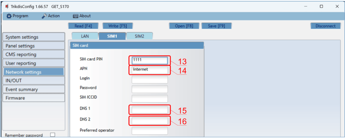
If a SIM card (or two SIM cards) is inserted in the communicator, the following settings must be made.
-
Enter “SIM card PIN” code.
-
Change the “APN” name. “APN” can be found on the website of the SIM card operator (“internet” is universal and works in many operator networks).
-
DNS1, DNS2: Google DNS server is set by default. Regardless of IP settings, make sure the DNS addresses match those supported by your ISP.
After finishing configuration, click Write [F5] and disconnect the USB cable.
Note
For a description of all GET settings, see Communicator settings.
3. Installation and wiring
3.1 Installation process
-
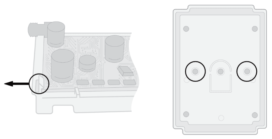
Remove the top cover and pull out the contact terminal.
-
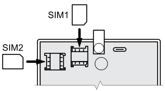
Insert SIM card into the holder.
-
Remove the PCB board from the bottom part of the case.
-
Fix the bottom part to a suitable place with screws.
-
Place the PCB board back into case, insert contact terminal.
-
Screw cellular antenna on.
-
Close the top cover.
-
If the LAN network will be used to transmit events to the CMS, a LAN cable must be connected to the communicator.
Note
One or two SIM cards can be inserted into the communicator. / Ensure that the SIM card is activated. / Ensure that mobile internet service (mobile data) is enabled if connected via IP channel. / To avoid entering the PIN code in TrikdisConfig, insert the SIM card into your mobile phone and turn off the PIN request function.
3.2 Installation in intrusion control panel enclosure panel
The GET communicator must be installed inside the intrusion control panel enclosure, which is protected by a lid tamper. It is mounted on the internal rear surface of the enclosure using the supplied industrial-grade double-sided acrylic foam mounting tape. The tape must be applied to a clean, dry surface with firm pressure to ensure reliable adhesion.
If the host enclosure does not allow secure installation as described above, the communicator may be installed in a separate tampered enclosure.
3.3 Schematics for wiring the communicator to a security control panel
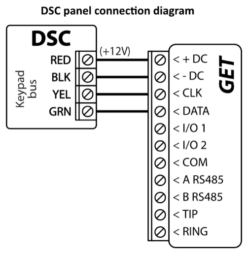
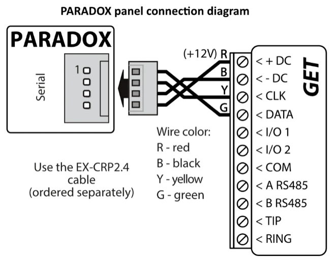
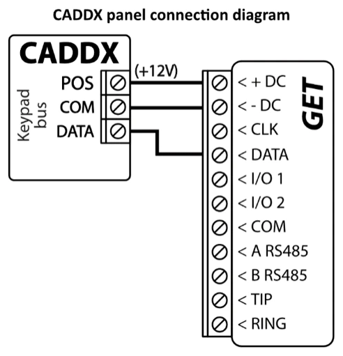
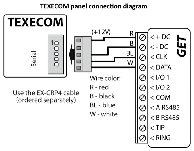
Following one of the schematics provided below, connect communicator to the control panel.
Note
In the diagrams below, +DC and −DC are the terminals marked +12 VDC and −12 VDC on the communicator, and A RS485 / B RS485 are the terminals marked A 485 / B 485.
3.3.1 DSC
3.3.2 PARADOX
3.3.3 CADDX
3.3.4 TEXECOM
3.3.5 INNERRANGE INCEPTION
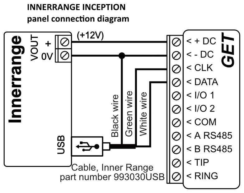
3.3.6 INNERRANGE INTEGRITI
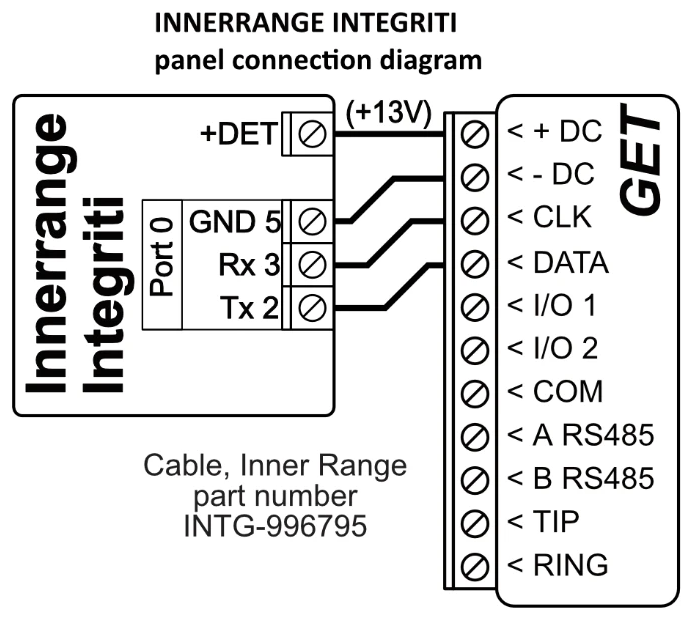
3.3.7 Honeywell Vista-15, Vista-20, Vista-48
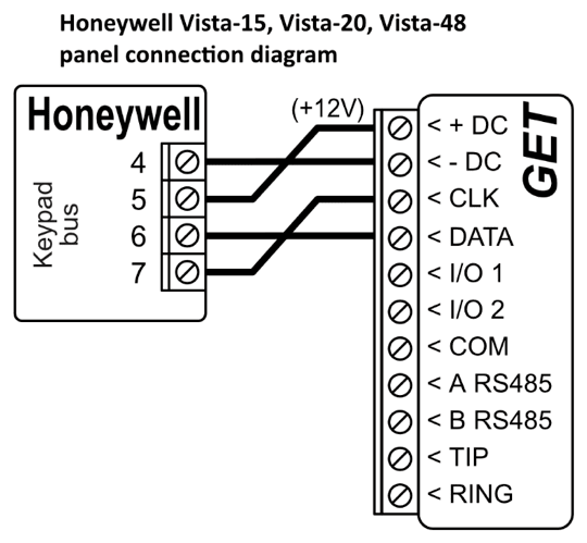
3.3.8 Control panel (telephone line communicator, TIP/RING)
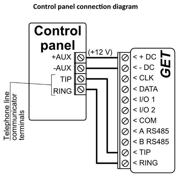
3.4 Schematic for wiring of the communicator to the keypad bus and telephone communicator (TIP/RING terminals) of the PARADOX SP/SP+/MG/MG+ control panel
Note
This connection needs communicator firmware 1.21 or later.
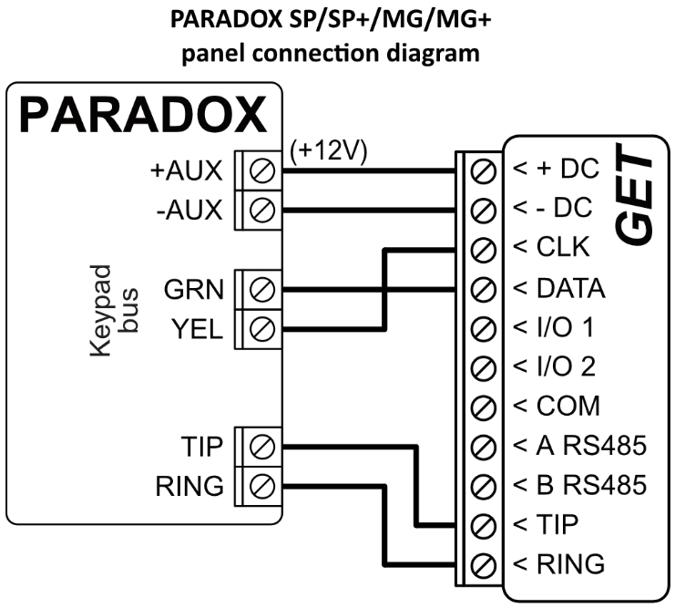
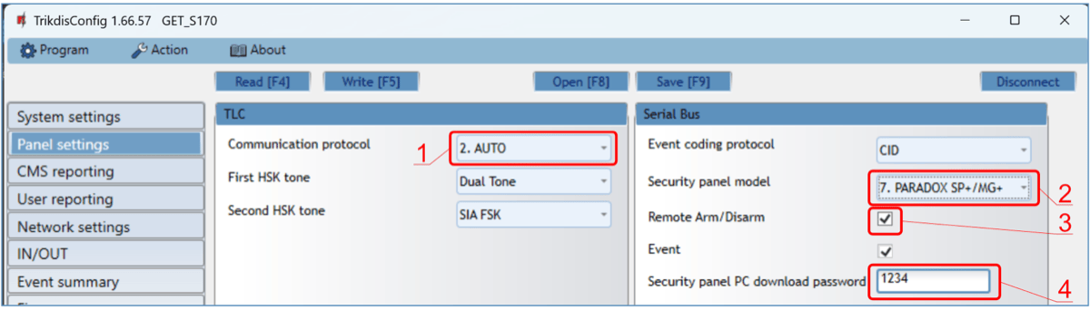
When connecting the communicator to the keypad bus and the TIP/RING terminals of the control panel, you must make the following settings for the GET communicator:
-
Select “AUTO”.
-
Select the control panel model “7. Paradox SP+/MG+ series KeyBus“.
-
Select “Remote Arm/Disarm” if you want users to be able to control the panel using the Protegus2 app using their own keypad code.
-
To directly control the security panel, enter the “Security panel PC download password”. It must match the password entered in the security panel.
The Paradox control panel must be programmed to transmit events to the CMS and for remote control from the Protegus2 application.
| Cell | Data | Cell | Data |
|---|---|---|---|
| 801 | ******** | 815 | 123456 |
| 811 | 1111 | 911 | 1234 |
| 812 | 2222 |
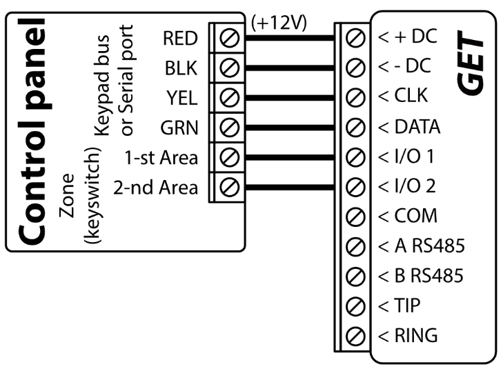
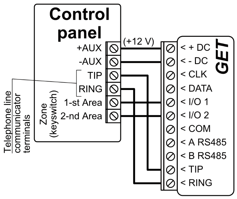
3.5 Schematic for wiring the communicator to the control panel keyswitch zone
Follow this schematic if the control panel will be armed/disarmed with a communicator PGM output turning on/off the panel’s keyswitch zone.
Note
GET communicator has 2 universal input / output terminals that can be set to the OUT (PGM) operating mode. The outputs (OUT) can control two areas of the security system. If you want to control the system in this way, in TrikdisConfig, in the "Panel settings" window, uncheck "Remote Arm/Disarm". The Protegus2 apps must be configured with the settings described in chapter 5.2 "Additional settings to arm/disarm the system using the control panel's keyswitch zone".
The communicator is connected to the keypad bus or serial bus of the control panel. / Arming/disarming the panel via keyswitch zone.
The communicator is connected to the telephone communicator (TIP/RING terminals) of the control panel. / Arming/disarming the panel via the keyswitch zone.
3.6 Schematics for input connection
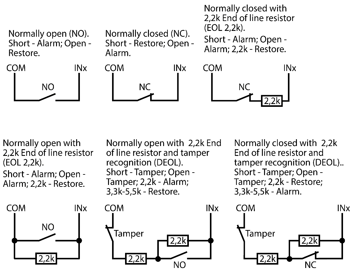
The communicator has 2 universal input / output terminals that can be set to input IN mode. NC, NO, NO / EOL, NC / EOL, NO / DEOL, NC / DEOL circuits can be connected to the input terminal. The input type can be changed in the TrikdisConfig window „IN/OUT” -> “Type”, or in the Protegus app under Advanced settings → IN/OUT, terminal 1 or 2 → Type.
Connect the input according to the selected input type (NO, NC, NC/EOL, NO/EOL, NO/DEOL, NC/DEOL), as shown in the schemes below:
3.7 Schematics for wiring a relay
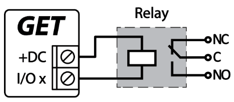
With relay contacts you can control (turn on/off) various electric appliances. The I/O terminal of the communicator must be set to an output (OUT) mode.
3.8 Turn on the communicator
To start the communicator, turn on the security control panel’s power supply. This LED indication on the GET communicator must show:
-
“POWER” LED illuminates green when the power is on;
-
“NETWORK LTE” LED illuminates green and blinks yellow when the communicator is registered to the cellular network.
Note
Sufficient strength of LTE signal is level three (three "NETWORK LTE" indicator flashes in yellow color). / If you count less yellow "NETWORK LTE" LED flashes, the network signal strength is insufficient. We recommend to select a different place to install the communicator, or to use a more sensitive cellular antenna. / If you see a different LED indication, it indicates a certain malfunction. Diagnose it by following the LED indication table in chapter 1.6 "LED indication of operation". / If the GET indication does not illuminate at all, check the power supply and connections.
4. Programming the control panel
4.1 Programming of control panels when the communicator is connected to the keypad bus or serial bus
Below it is described how to program the security control panel so that the GET communicator could read events from the panel and control it remotely.
To enable remote control of the security panel, make sure that the checkbox “Remote Arm/Disarm” is selected in the TrikdisConfig window “Panel settings”.
4.1.1 DSC
DSC panels do not need to be programmed.
4.1.2 PARADOX
Paradox control panels need to be programmed only for direct control with Protegus2. You do not need to program Paradox panels for reading events.
For remote control of Paradox panels, you need to set up a PC download password. This password must match the password which was set in the TrikdisConfig window “Panel settings”, when the checkbox next to “Remote Arm/Disarm” was selected.
To set this password, with the keyboard connected to the security control panel:
-
For MAGELLAN, SPECTRA series: go to cell 911 and enter 4-digit PC download password.
-
For DIGIPLEX EVO series: go to cell 3012 and enter 4-digit PC download password.
4.1.3 TEXECOM
Texecom control panels need to be programmed for both reading events and remote control.
You need to set the Texecom panel’s “UDL passcode”. This password must match the password which was set in the TrikdisConfig window “Panel settings”, when the box next to “Remote Arm/Disarm” was selected.
The security control panel can be programmed with Texecom software - Wintex. Enter “UDL passcode” (4-digit code) in the “Communication Options” window, “Options” tab.
Also, you can program with a keypad connected to the security control panel:
-
Enter the 4-digit installer’s code and press the [Menu] button to enter the programming menu.
-
Press the [9] key immediately afterwards.
-
Press [7][6], and then [2]. Enter the 4-digit “UDL passcode” (“UDL passcode” must match the GET communicator’s “PC login password”).
-
Press [Yes] and leave the programming mode by pressing [Menu].
4.1.4 UTC INTERLOGIX (CADDX)
With the keyboard connected to the security control panel:
-
Press [*][8] and enter the installer’s code (default - 9713).
-
Enter the device number assigned to the connected communicator (default - 0).
-
Set the settings below for each row. In sequence, enter the position, segment number and the required setting. Clicking [*] (asterisk) will return you to the local input field.
| Position | Segment | Setting |
|---|---|---|
| 23 | 3 | 12345678 |
| 37 (not necessary) | 3 | 12345678 |
| 37 (not necessary) | 4 | 1234567* |
| 90 | 3 | 12345678 |
| 93 | 3 | 12345678 |
| 96 | 3 | 12345678 |
| 99 | 3 | 12345678 |
| 102 | 3 | 12345678 |
| 105 | 3 | 12345678 |
| 108 | 3 | 12345678 |
After having programmed all the fields listed, press [Exit] twice to exit the programming mode.
4.1.5 INNERRANGE
Innerrange Inception security control panel version must be 2.3.0.3507-r0 or higher.
The control panel must be connected to the internet. Connect to Innerrange Inception by entering: https://skytunnel.com.au/inception/SERIALNUMBER, where SERIALNUMBER is the number of the controller that you can find on the panel’s enclosure.
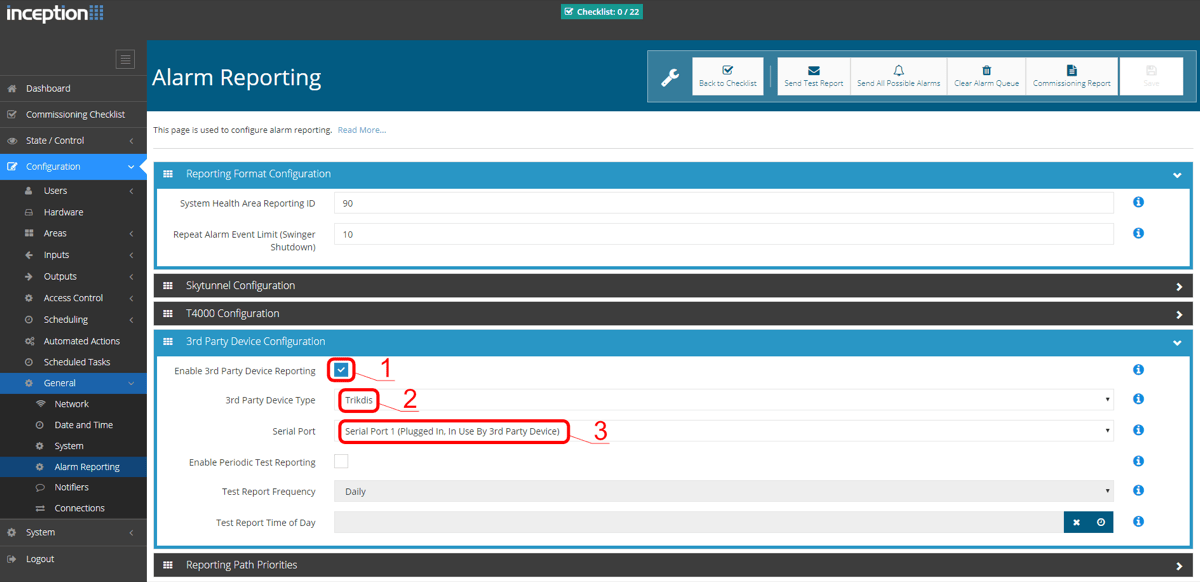
Open Configuration > General > Alarm Reporting. In the 3rd Party Device Configuration settings group you need to enter:
-
Enable 3rd Party Device Reporting - select this checkbox.
-
3rd Party Device Type - set “Trikdis”.
-
Serial port - set “Serial Port 1 (Plugged In, In Use By 3rd Party Device)”.
-
Save settings and exit the application.
4.1.6 HONEYWELL ADEMCO VISTA
Follow these steps for Honeywell Ademco Vista-20 and Honeywell Ademco Vista-48 panels. The panel’s firmware version must be V5.3 or higher. With a keypad that is connected to the panel:
-
Enter the programming mode. Enter the installer code 4][1][1][2] and after that [8][0][0] . Alternatively, turn on the panel‘s power supply. In 50 seconds after the power supply is turned on, press the buttons [*] and [#] at the same time (this method can be used when programming mode was exited by pressing in keypad [*][9][8] ).
-
Turn on the sending of Contact ID events via LRR. Press [*][2][9][1][#] in keypad.
-
When using the „Remote Arm/Disarm“ function, allow to use the 2nd AUI address. In keypad press [*][1][8][9][1][1][#] .
Exit the programming mode. In keypad press [*][9][9].
4.2 Programming of control panels when the communicator is connected to the TIP/RING terminals of the control panel
For the control panel to send events via the landline dialer, it must be turned on and properly set up. Following the panel’s programming manual, configure the control panel’s landline dialer:
-
Turn on the panel’s PSTN landline dialer.
-
Enter the monitoring station receiver’s telephone number (you can use any number longer than 4 digits. The GET communicator will pick up and answer when the panel calls to any phone number).
-
Choose DTMF mode.
-
Select Contact ID communication protocol.
-
Enter the panel’s 4 digit account number.
The control panel zone to which the GET output OUT is connected should be set to keyswitch zone for arming/disarming the control panel remotely.
Note
Keyswitch zone can be momentary (pulse) or level. By default, the GET controllable output OUT is set to 3 second pulse mode. You can change the impulse duration or change to level mode in Protegus2 settings. See chapter 5.2 "Additional settings to arm/disarm the system using the control panel's keyswitch zone".
4.2.1 PROGRAMMING HONEYWELL VISTA LANDLINE DIALER
Using the control panel’s keypad enter these sections and set them as described:
-
*41 – enter monitoring station receiver telephone number;
-
*43 – enter control panel’s account number;
-
*47 – set the Tone dial to [1] and enter the number of dial attempts;
-
*48 – use default setting, *48 must be set to 7;
-
*49 – Split/Dual message. *49 must be set to 5;
-
*50 – delay for sending burglary alarm events (optional). Default value is [2,0]. With it the event message transmission will be delayed for 30 seconds. If you want the message to be sent immediately, set [0,0].
When all required settings are set, it is necessary to exit programming mode. Enter *99 in keypad.
4.2.2 SPECIAL SETTINGS FOR HONEYWELL VISTA 48 PANEL
If you want to use GET communicator with Honeywell Vista 48 panel, set the following sections as described:
| Section | Data | Section | Data | Section | Data |
|---|---|---|---|---|---|
| *41 | 1111 (receiver telephone number) | *60 | 1 | *69 | 1 |
| *42 | 1111 | *61 | 1 | *70 | 1 |
| *43 | 1234 (panel account number) | *62 | 1 | *71 | 1 |
| *44 | 1234 | *63 | 1 | *72 | 1 |
| *45 | 1111 | *64 | 1 | *73 | 1 |
| *47 | 1 | *65 | 1 | *74 | 1 |
| *48 | 7 | *66 | 1 | *75 | 1 |
| *50 | 1 | *67 | 1 | *76 | 1 |
| *59 | 0 | *68 | 1 |
When all required settings are set, it is necessary to exit programming mode. Enter *99 in keypad.
4.2.3 UTC INTERLOGIX(CADDX)
Programming of the Interlogix NX-4V2 (NX-6V2, NX-8V2) control panel when the communicator is connected to the TIP/RING terminals of the control panel.
| Keypad Entry | Description | |
|---|---|---|
| *89713 | Enter programming mode | |
| 0# | ||
| Location 0 | 0# | |
| Location 0 | 1234# | |
| Location 1 | 1# | |
| Location 1 | 1234# | |
| Location 2 | 2# | |
| Location 2 | 1*# | |
| Location 4 | 4# | All zones LEDs are ON (segment 1) |
| Location 4 | 12345678* | All zones LEDs are ON (segment 2) |
| Location 4 | 12345678*# | |
| Location 23 | 23# | All zones LEDs are ON (segment 3) |
| Location 23 | ** | All zones LEDs are ON (segment 3) |
| Location 23 | 12345678*# | All zones LEDs are ON (segment 3) |
| Location 37 | 37# | All zones LEDs are ON (segment 3) |
| Location 37 | ** | All zones LEDs are ON (segment 4) |
| Location 37 | 12345678* | |
| Location 37 | 12345678*# | |
| EXIT EXIT | Exit programming mode |
5. Remote control
5.1 Adding the security system to Protegus2 app
With Protegus2 users will be able to control their alarm system remotely. They will see the status of the system and receive notifications about system events.
-
Download and launch the Protegus2 application or use the browser version: web.protegus.app.



-
Log in with your user name and password or register and create new account.
Important
When adding the GET communicator to Protegus2 check if:
-
The inserted SIM card is activated and the PIN code is either entered or disabled;
-
Or a LAN cable is connected.
-
"Protegus cloud" is enabled. See User reporting;
-
Power supply is connected ("POWER" LED illuminates green);
-
Registered to the network ("NETWORK LTE" LED illuminates green and blinks yellow).
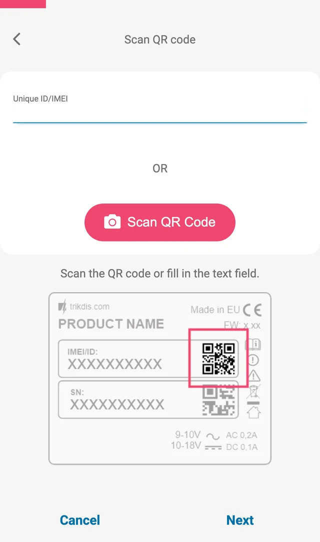
- Click “Add new system” and enter the GET’s “IMEI/Unique ID” number. This number can be found on the device and the packaging sticker. Click “Next”.
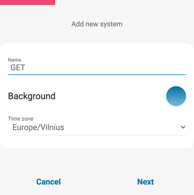
- Enter the system „Name”. Click "Next".
5.2 Additional settings to arm/disarm the system using the control panel’s keyswitch zone
Important
The control panel zone to which the GET output OUT is connected to has to be set to keyswitch mode.
Follow the instructions below if the security control panel will be controlled with a GET PGM output, turning on/off the control panel keyswitch zone.
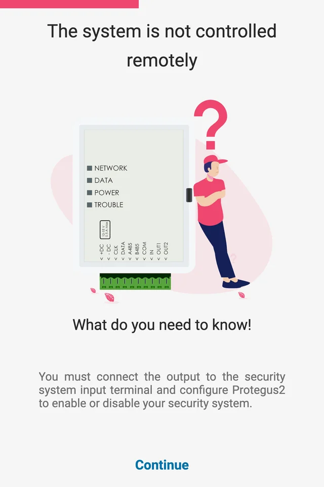
- Click „Continue“.
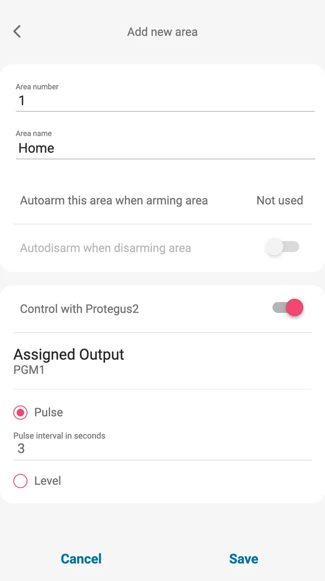
- Enter “Area name”. Enable PGM output control using the Protegus2 application.
-
Select “Pulse” or “Level”, depending on how the keyswitch zone type is configured. If necessary, you can change the "Pulse" interval.
-
Click „Save“.
-
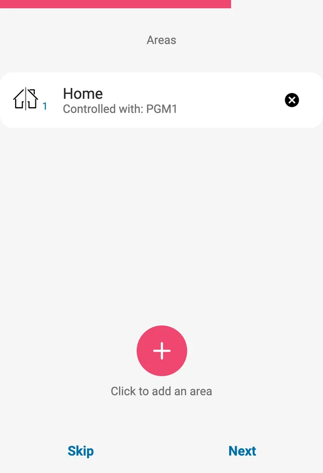
If there is another Area for the security system, then you need to click “Click to add an area”. Setting up the PGM output is similar to that described above.
-
After completing the settings, click the “Skip” button.
5.3 Arming/disarming the alarm system with Protegus2
-
In the “System Home Screen” window, click on the “Disarm” status icon.
-
Protegus2 will receive a message about a change in the status of the security system and the status icon will change its state.
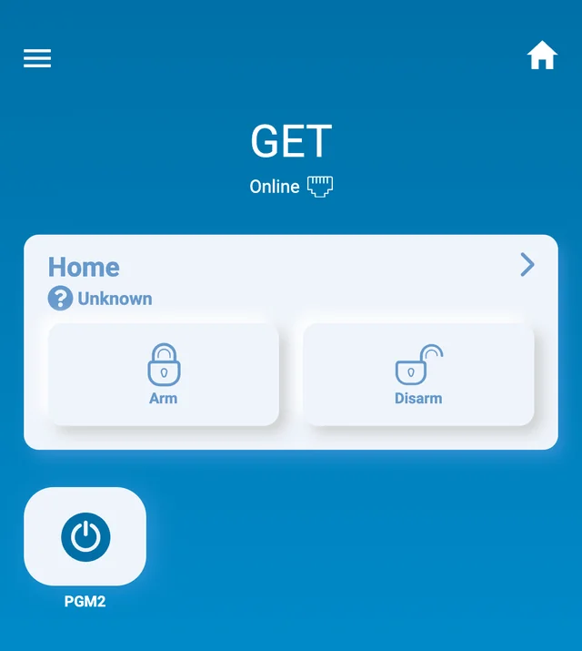
6. Communicator settings
Most GET settings described below can be changed in the Protegus app or in TrikdisConfig; settings and actions available in only one tool are marked. What each setting does is described once; each section shows where to find it in each tool. Names in brackets are the Protegus app's labels where they differ from TrikdisConfig's.
6.1 Connecting to the communicator
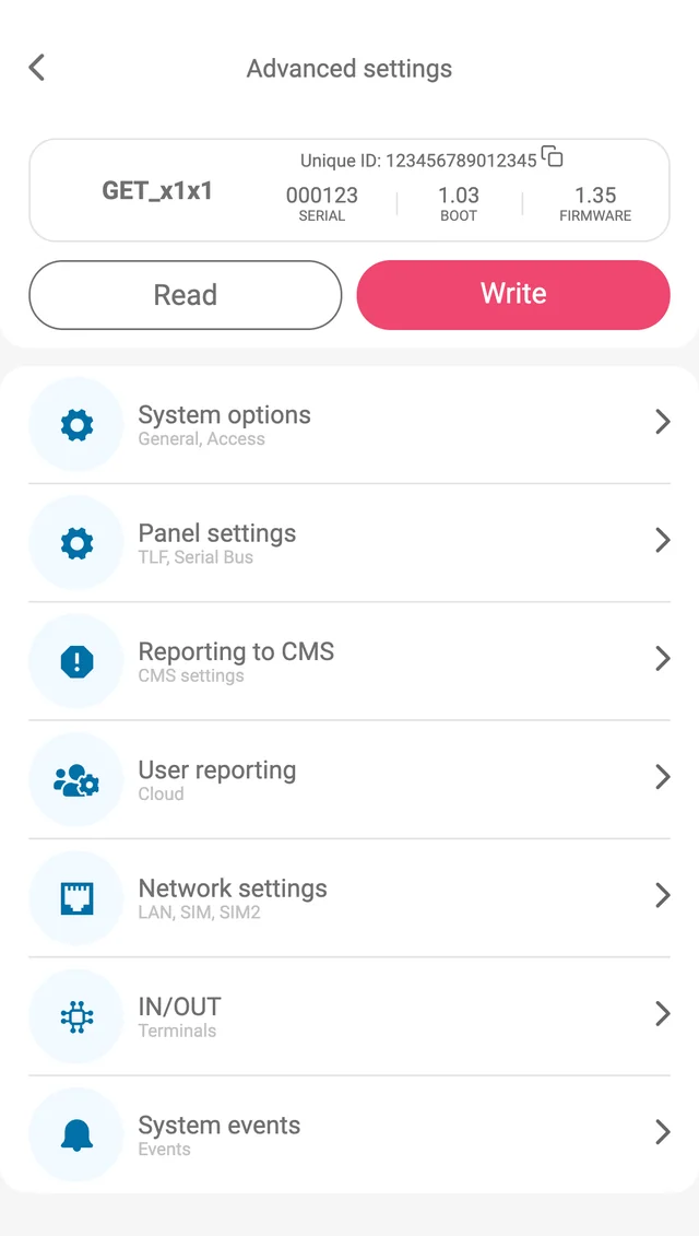
Open the system in the Protegus app and go to Settings → Advanced settings (see Quick configuration). The top of each screen shows the connected device: Unique ID (IMEI), Serial, Firmware and Boot version.
The settings are grouped in the menu as System options, Panel settings, Reporting to CMS, User reporting, Network settings, IN/OUT and System events. After changing settings, tap Write to save them to the communicator. Read loads the current settings from the communicator again.
After connecting the GET communicator and clicking Read [F4], TrikdisConfig will provide information about the connected device in the status bar:

| Object | Description |
|---|---|
| IMEI/Unique ID | Device IMEI number |
| Status | Operating condition |
| Device | Device type (GET should be shown) |
| SN | Device serial number |
| BL | Bootloader version |
| FW | Device firmware version |
| HW | Device hardware version |
| State | Connection to program type (via USB or remote) |
| Administrator | Access level (shown after access code is approved) |
After pressing Read [F4], the program will read and show the settings which are set in the GET. Set the necessary settings according to the TrikdisConfig window descriptions given below.
6.2 System settings
In the Protegus app: Advanced settings → System options → System general (account numbers, time set) and System options → Access (codes and installer permissions).
Where Account No. and Device account No. are depends on the hardware version and firmware. On hardware version x1x1 with firmware 1.31 or later they are in Reporting to CMS → CMS settings → Primary channel (Primary Account no.; Parallel Account no. on the parallel channel) and in Reporting to CMS → Settings (Device account No.), and System general shows only Time set. Otherwise they are in System general.
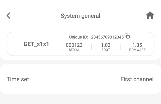 Hardware x1x1
 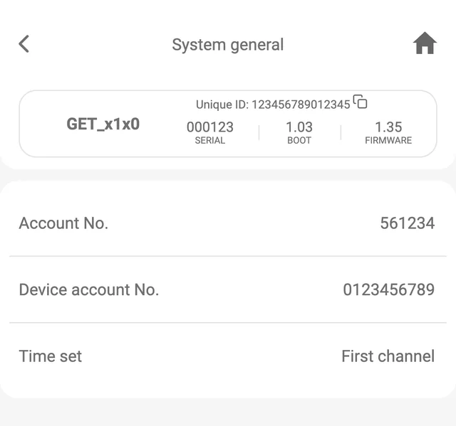 Hardware x1x0
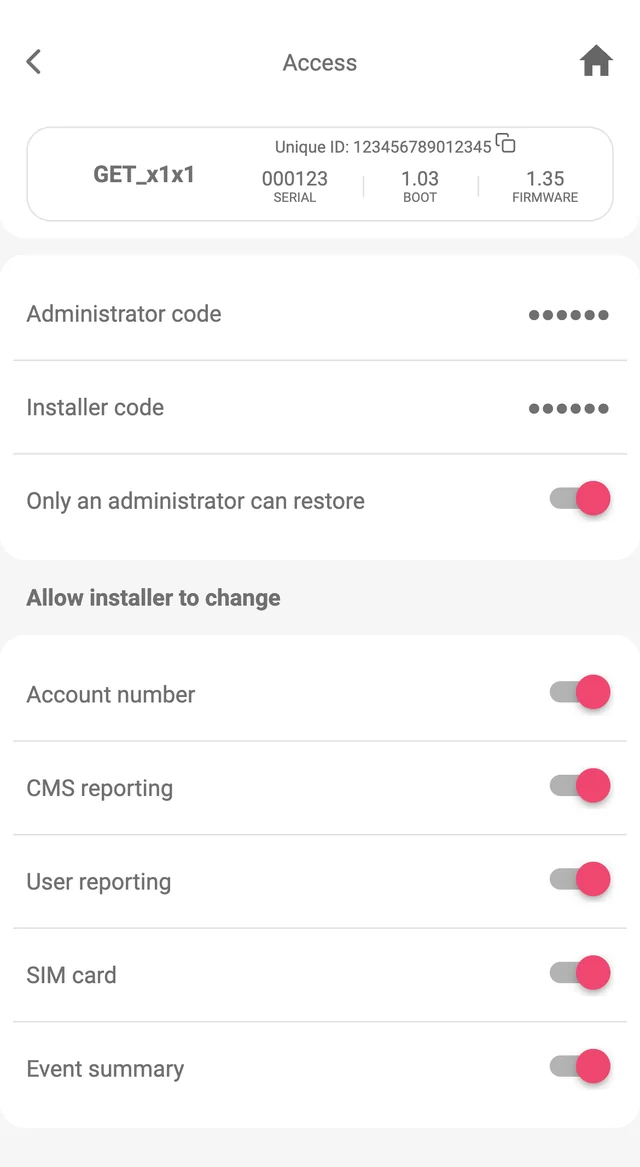
In TrikdisConfig, open the System settings window.
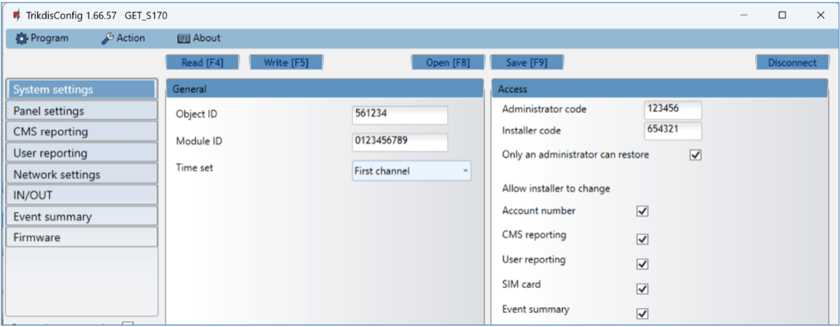
“General” settings group
-
Object ID (Account No.) – if the events will be sent to the CMS (Central Monitoring Station), enter the account number provided by the CMS (6 characters hexadecimal number, 0-9, A-F. Do not use FFFE, FFFF Object ID).
-
Module ID (Device account No.) – enter the identification number of the module.
-
Time set - select which server to use for time synchronization.
“Access” settings group
When setting up the communicator GET there are two levels of access for, the administrator and the installer:
-
Administrator code - allows you to access all configuration fields (default code - 123456).
-
Installer code - limited access for configuring the communicator (default code - 654321).
-
Only an administrator can restore - if the box is checked, factory settings can be restored only by entering the administrator code.
-
Allow installer to change – the administrator can specify which settings can be changed by the installer: Account number, CMS reporting, User reporting, SIM card and Event summary.
Installer access in the Protegus app
When the communicator is opened with the installer code, the Protegus app hides Administrator code and Only an administrator can restore, and shows the settings the administrator did not allow as read-only. In the app, the SIM card permission also covers the LAN settings, and where the account numbers are in the CMS settings (see above), they follow the CMS reporting permission.
6.3 Panel settings
In the Protegus app: Advanced settings → Panel settings → TLF (TIP/RING connection) and Panel settings → Serial Bus (keypad or serial bus connection).
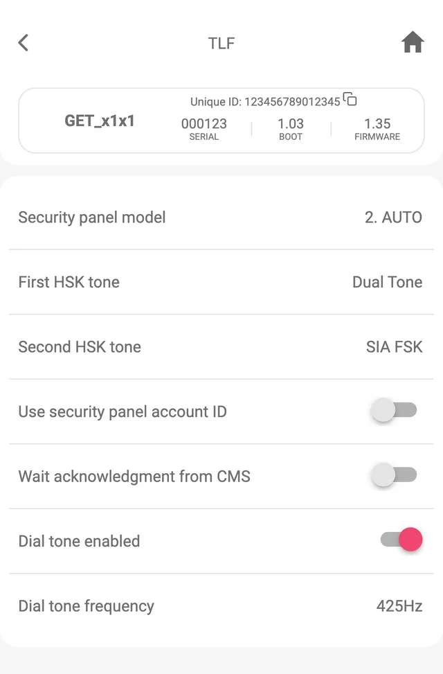
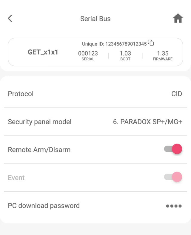
In TrikdisConfig, open the Panel settings window.
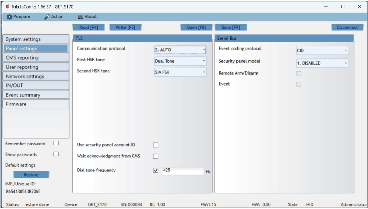
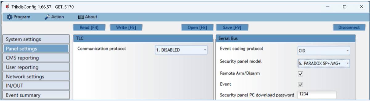
“TLC” settings group
The communicator is connected to the TIP RING terminals of the telephone communicator of the control panel.
-
Communication protocol (Security panel model) – enable/disable DTMF landline interface on the communicator.
-
First HSK tone / Second HSK tone – handshake tone of control panel.
-
Use security panel account ID – if the box is marked with a check mark, the communicator will not send the value set in the "Object ID" field, but the object number entered in the control panel.
-
Wait acknowledgment from CMS – if the box is marked with a check mark, after sending each event message, the communicator will wait for confirmation from the IP receiver that it has successfully received the message. If the communicator does not receive a confirmation signal, it will not generate a “kiss-off” signal. If the communication end signal is not received, the control panel's telephone communicator will repeat the event message.
-
Dial tone frequency - the frequency at which the communicator communicates with the control panel through the telephone communicator.
In the Protegus app, the TLF screen also has Dial tone enabled, which turns the dial tone on or off; Dial tone frequency can only be changed while it is on.
“Serial bus” settings group
The communicator is connected to the control panel via a Serial Bus.
-
Event coding protocol (Protocol) – select the event reporting protocol (CID or SIA).
-
Security panel model – select the control panel model that will be connected to the communicator.
-
Remote Arm/Disarm – when the checkbox is selected, the GET will directly control the control panel remotely. This setting will be visible only for directly controlled panels. For direct control of the control panels you need to change the panel settings, as described in section 4.1 “Programming of control panels when the communicator is connected to the keypad bus or serial bus”.
-
Event – check the box so that the communicator sends events to the CMS and to Protegus2. In the Protegus app this switch is shown but cannot be changed.
-
Security panel PC download password (PC download password; for Texecom, the UDL passcode) - for the direct control of Paradox and Texecom control panels you need to enter the PC/UDL password. It must match the password that was entered in the control panel. How to change this password is described in section 4.1 “Programming of control panels when the communicator is connected to the keypad bus or serial bus”.
6.4 CMS reporting
Events can be sent over several channels of communication. The primary and parallel communication channels can operate simultaneously, this way the communicator can send events to two receivers at the same time. Backup channels can be assigned for both primary and parallel channels, which will be used when the connection via the primary or parallel channel is interrupted.
Communication is encoded and password protected. With the TRK protocols, a TRIKDIS receiver is required for receiving and sending event information to the monitoring programs (DC-09 and TL150 are for universal and SUR-GUARD receivers, see Protocol below):
- For connection over IP - software receiver IPcom Windows/Linux, hardware IP/SMS receiver RL14 or multichannel receiver RM14.
6.4.1 Receiver channels
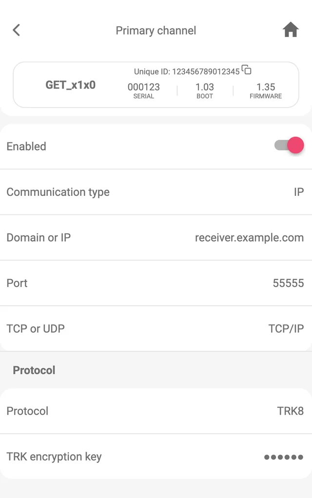
In the Protegus app: Advanced settings → Reporting to CMS → CMS settings, then Primary channel, Backup channel or Parallel channel (Parallel primary channel, Parallel backup channel). Turn on Enabled to show the channel's settings.
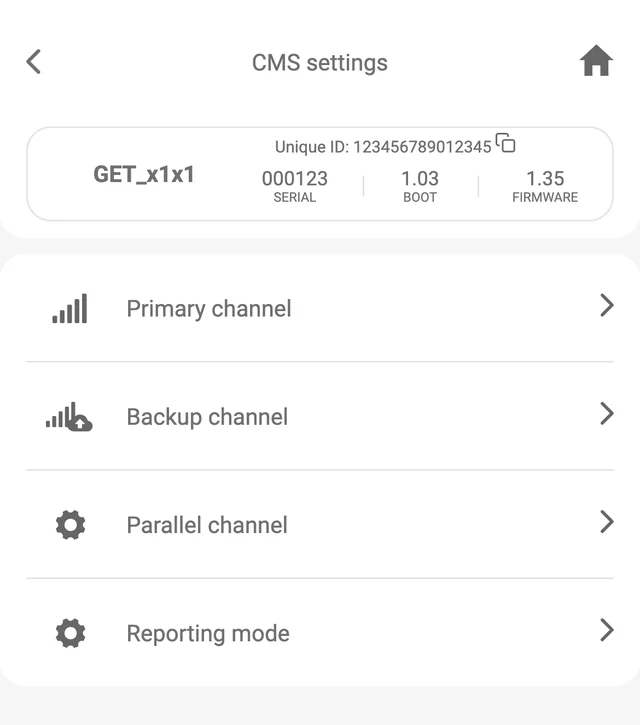
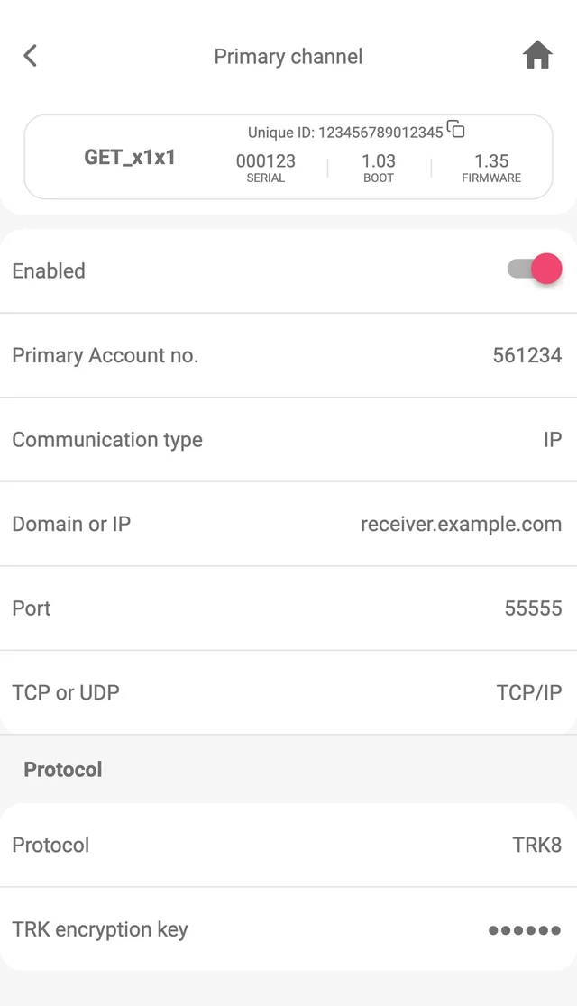 Hardware x1x1
  Hardware x1x0
In TrikdisConfig, open the CMS reporting window, CMS settings tab.
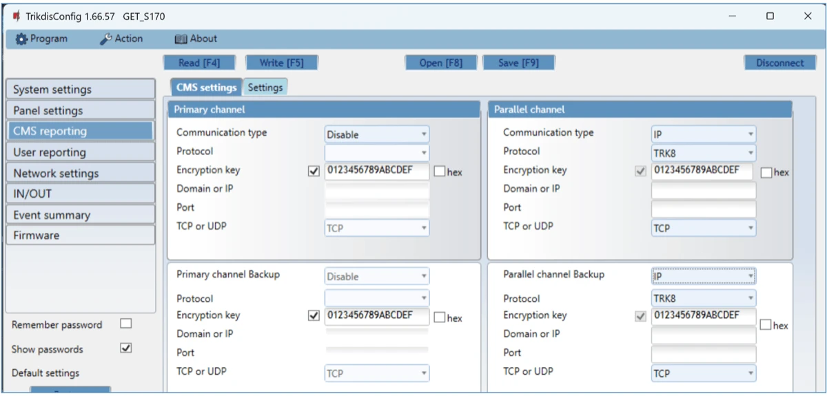
“Primary channel” settings group
-
Communication type - select the method of communication with the monitoring station receiver (IP).
-
Protocol - select in which coding the events should be sent: TRK8 (to TRIKDIS receivers), DC-09_2007 or DC-09_2012 (to universal receivers), TL150 (to SUR-GUARD receivers).
-
Encryption key (TRK encryption key; for DC-09 protocols, Enable encryption key and DC-09 encryption key, with HEX for a key in hexadecimal) - message encryption key. The key written to the communicator must match the receiver’s key. In the Protegus app, the TRK encryption key takes up to 6 characters and the DC-09 encryption key up to 16 (32 in HEX).
-
Domain or IP - enter the domain or IP address of the receiver.
-
Port - enter the network port number of the receiver.
-
TCP or UDP - select in which protocol (TCP or UDP) the events should be sent.
“Primary channel Backup” settings group
Enable the backup channel mode to send events via backup channel if connection via primary channel is lost. Backup channel settings are same as described above.
“Parallel channel” settings group
Events are transmitted in parallel with the primary channel through this channel. When the second channel is enabled, events can be sent simultaneously to two receivers (e.g., local and centralized monitoring stations). Parallel channel settings are the same as described above.
6.4.2 Test, ping and reporting mode
In the Protegus app: Advanced settings → Reporting to CMS → Settings (test, ping, backup timing, receiver and line numbers) and Reporting to CMS → CMS settings → Reporting mode (connection order).
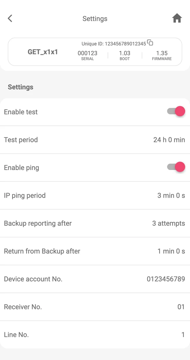 Hardware x1x1
 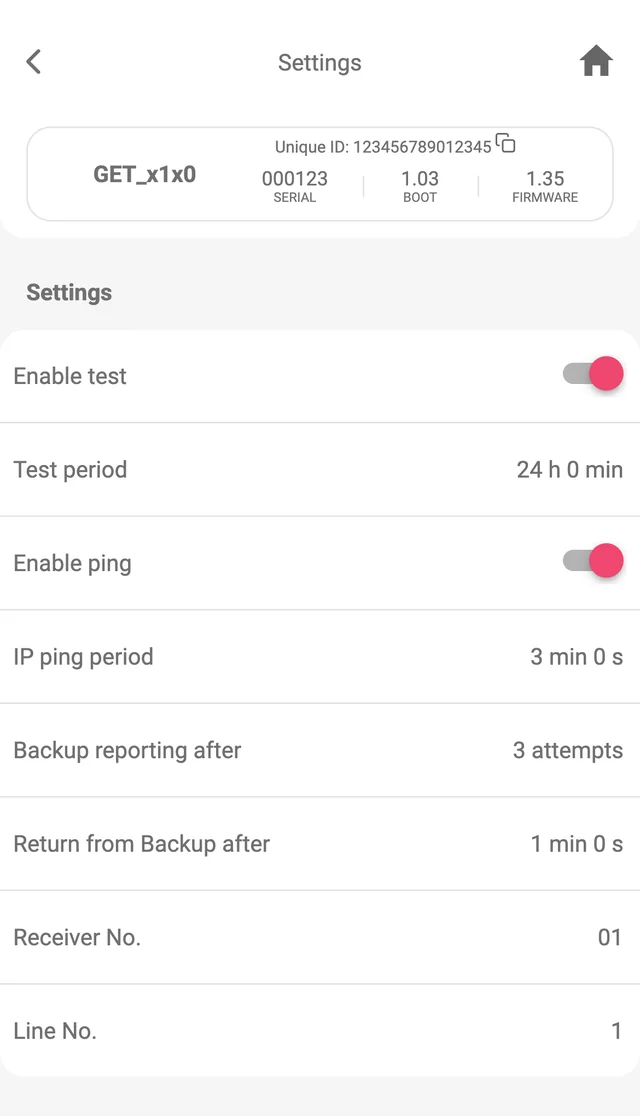 Hardware x1x0
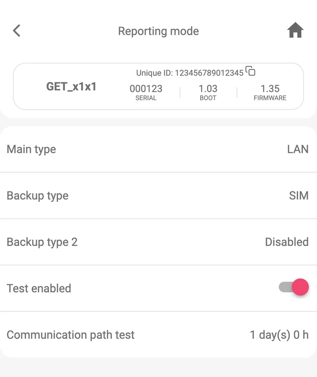
The app has an on/off switch next to each period: Enable test for Test period, Enable ping for IP ping period, and Test enabled for Communication path test. In Reporting mode, the connection types are named LAN, SIM (SIM1) and SIM2.
In TrikdisConfig, open the CMS reporting window, Settings tab.
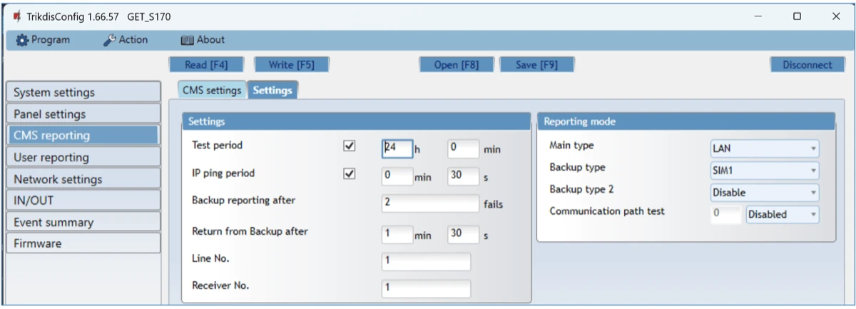
“Settings” settings group
-
Test period - TEST event period for testing the connection. Test events are sent as Contact ID messages and forwarded to the monitoring software.
-
IP ping period – period for sending internal PING heartbeats. These messages are only sent via IP channel. The receiver will not forward PING messages to the monitoring software to avoid overloading it. Notifications will only be sent to the monitoring software if the receiver fails to receive PING messages from the device within the set time.
By default, the “Connection lost” notification will be transmitted to the monitoring software if the PING message is not received by the receiver over a time period three times longer than set in the device. E.g. if the PING period is set for 3 minutes, the receiver will transfer the “Connection lost” notification if a PING message is not received within 9 minutes.
PING messages keep the active communication session between the device and the receiver. An active session is required for remote connection, control and configuration of the device. We recommend setting the PING period for no more than 5 minutes.
-
Backup reporting after - indicates the number of unsuccessful attempts to send the message via “Primary” channel. If device fails to transmit specified number of times, the device will connect to transmit the messages via “Backup” channel.
-
Return from backup after - time after which the communicator GET will attempt to reconnect and transmit messages via the Primary channel.
-
Line No. - enter line number of the receiver.
-
Receiver No. - enter the receiver number.
“Reporting mode” settings group
For setting parameters on how the control panel will communicate with the CMS channels and with Protegus2. The connection types are specified in order. If the control panel fails to connect using the “Main type” connection , it switches to the “Backup type”, and so on. If the backup connection type was successful in transmitting the message to the CMS, then the “Return to main” connection type will be attempted after the specified time interval.
-
Main type – select a connection type (LAN, SIM1, SIM2) with the CMS receiver and Protegus2.
-
Backup type – select a connection type (LAN, SIM1, SIM2) with the CMS receiver and Protegus2.
-
Backup type 2 – select a connection type (LAN, SIM1, SIM2) with the CMS receiver and Protegus2.
-
Communication path test – specify the time period for which the selected connection types should be tested (LAN, SIM1, SIM2).
6.5 User reporting
Protegus2 service allows users to remotely monitor and control the communicator. For more information about Protegus2 service, visit web.protegus.app.
In the Protegus app: Advanced settings → User reporting → Cloud.
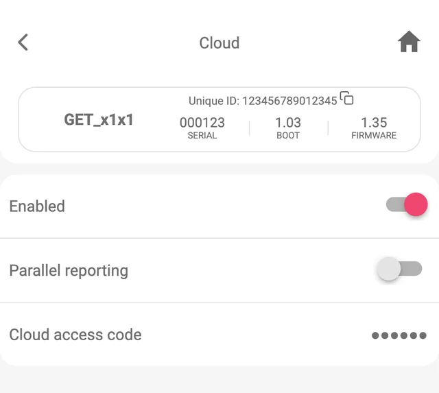
In TrikdisConfig, open the User reporting window, PROTEGUS cloud tab.
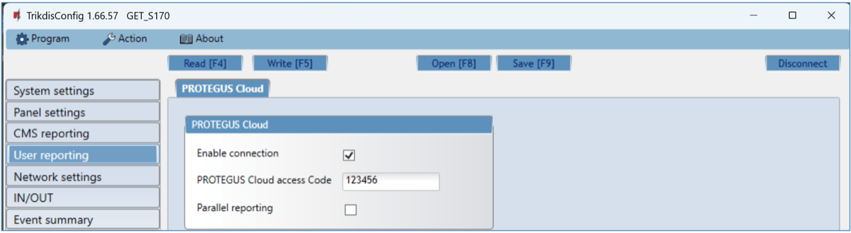
“Protegus Cloud” settings group
-
Enable connection (Enabled) – enable the Protegus2 service, the GET communicator will be able to exchange data with Protegus2 app and to be remotely configured via TrikdisConfig.
-
Protegus Cloud access Code (Cloud access code) - 6-digit code for connecting to the Protegus2 app (default - 123456).
-
Parallel reporting (shown in the app when the firmware supports it) – allow parallel report sending using the primary channel and to Protegus2. Reports will only be sent to Protegus2 and to users after they’ve been sent to the security company.
6.6 Network settings
6.6.1 LAN
These settings must be made if the communicator is connected to a LAN network.
In the Protegus app: Advanced settings → Network settings → LAN. Static IP, Subnet mask, Default gateway, DNS1 and DNS2 can only be changed while Use DHCP is off.
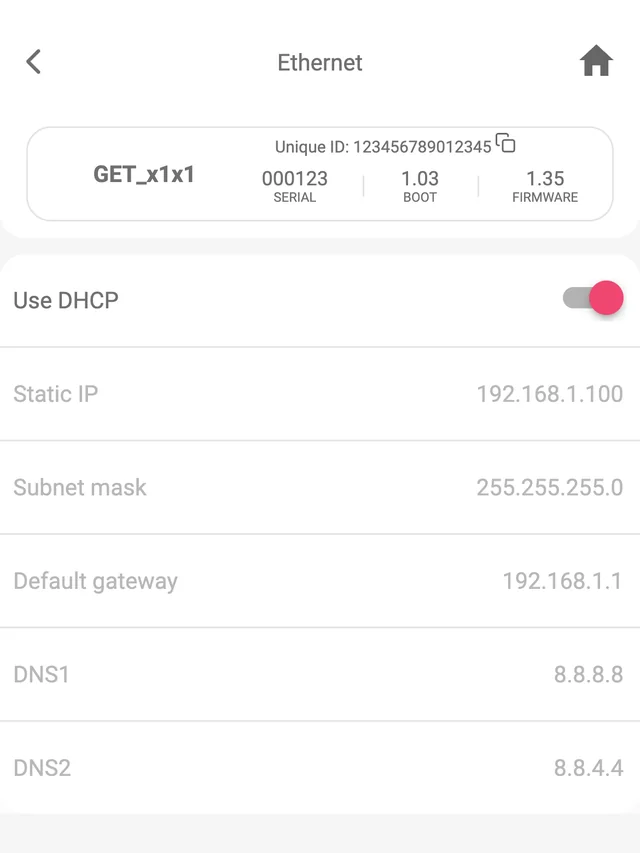
In TrikdisConfig, open the Network settings window, LAN tab.
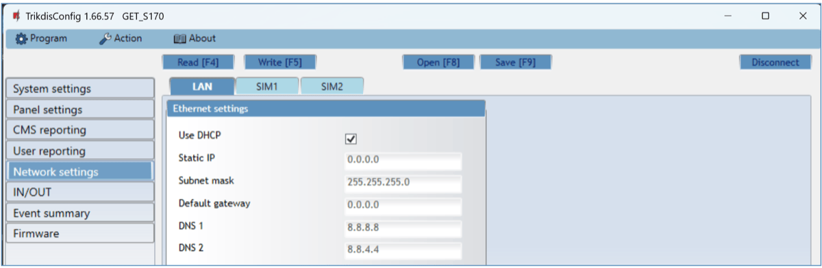
“Ethernet settings” settings group
- Use DHCP - check the box to have the communicator automatically register to the network. If the auto-register fails, you will need to enter it manually:
-
Static IP – static IP address for when manual registering mode is set.
-
Subnet mask – subnet mask for when manual registering mode is set.
-
Default gateway – gateway address for when manual registering mode is set.
- DNS1, DNS2 - (Domain Name System) identifies the server that specifies the IP address of the domain. Used when domain is set in the communication channel “Domain or IP” field (not IP address). Google DNS server is set by default. Regardless of IP settings, make sure the DNS addresses match those supported by your ISP.
6.6.2 SIM1 and SIM2
These settings must be made for each SIM card inserted into the communicator. The SIM1 and SIM2 slots have the same settings.
Important
- Ensure that the SIM card is activated and working before using it.
- Ensure that mobile data service is enabled.
In the Protegus app: Advanced settings → Network settings → SIM (SIM1) or SIM2.
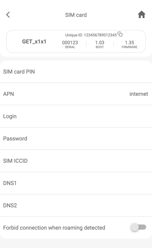
The Protegus app does not show Preferred operator for GET; this screen has a Forbid connection when roaming detected switch instead. On hardware revision M15 with firmware 1.17 or later, the SIM screen also has Generation and Bands, which limit the mobile network technology and frequency bands the communicator uses.
In TrikdisConfig, open the Network settings window, SIM1 or SIM2 tab.
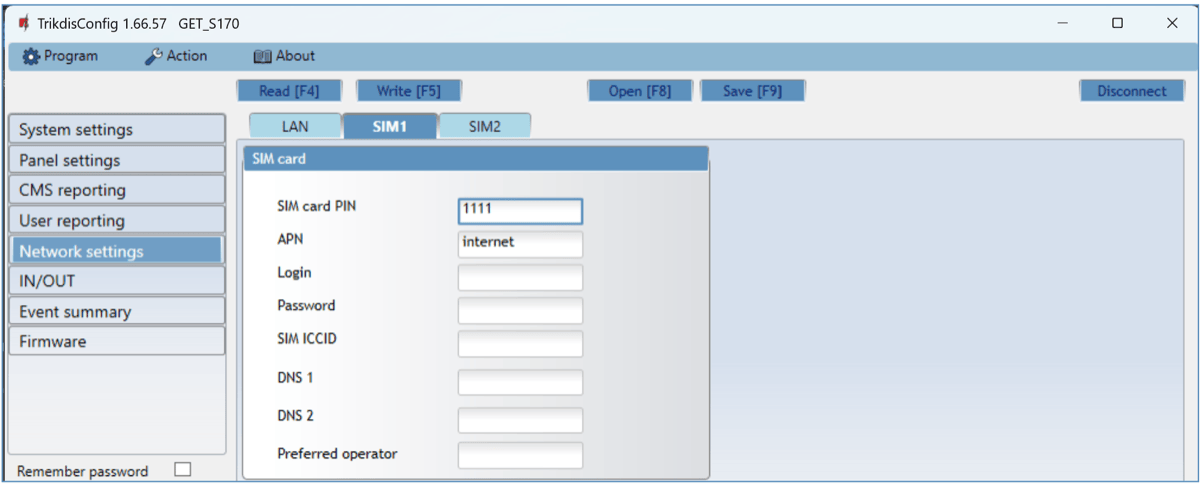
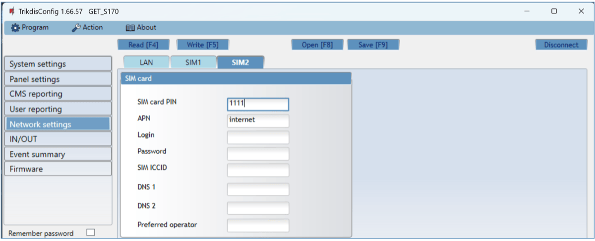
“SIM card” settings group
-
SIM card PIN - enter the SIM card PIN code. This code can be disabled by inserting the SIM card into a mobile phone and disabling the request. If you disabled the SIM card PIN request, leave the default value in this field.
-
APN - enter APN (Access Point Name). It is required for connecting the communicator to the internet. APN can be found on the website of the SIM card operator (“internet” is universal and works in the networks of many operators).
-
Login, Password - if required, enter the user name (login) and password for connection to the internet.
-
SIM ICCID - enter the ICCID number of the SIM card if you want the communicator to work only with this SIM card.
-
DNS1, DNS2 - (Domain Name System) identifies the server that specifies the IP address of the domain. Used when domain is set in the communication channel Domain or IP field (not IP address). Google DNS server is set by default. Regardless of IP settings, make sure the DNS addresses match those supported by your ISP.
- Preferred operator – after entering the mobile network operator code, the communicator will connect only to the network of the selected operator. The mobile operator code consists of MCC and MNS codes. Only in TrikdisConfig.
6.7 IN/OUT
The communicator has 2 universal (input / output) terminals. The table can set the terminal operating mode (Disabled, IN, OUT). The input must specify the type of circuit to be connected NC, NO, NO / EOL, NC / EOL, NO / DEOL, NC / DEOL.
Additional sensors can be connected to the communicator inputs. When the sensor is triggered, the communicator will send an event message. The input is assigned a Contact ID (SIA) code, which will be sent to CMS and Protegus2.
In the Protegus app: Advanced settings → IN/OUT, then select terminal 1 or 2. Set Function (Disabled, IN, OUT) and, for an input, Type. The Alarm and Tamper sections hold the event and restore messages sent when the input is triggered.
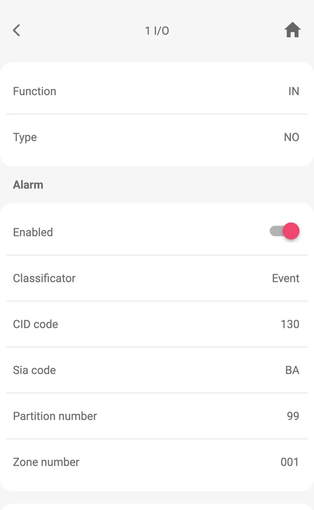
In TrikdisConfig, open the IN/OUT window.
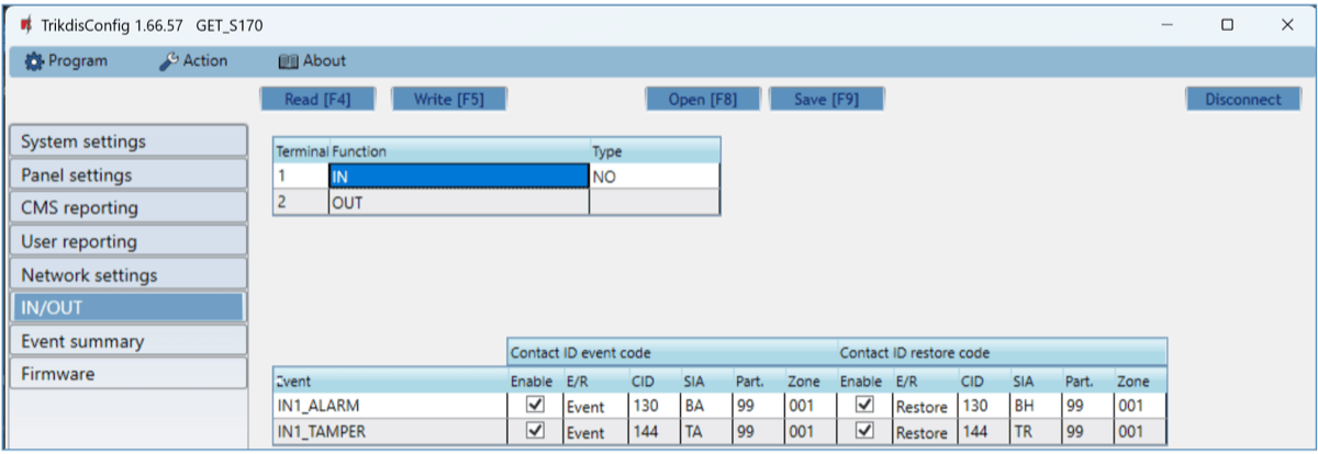
-
Enable (Enabled) – checked event fields where messages will be sent to CMS and Protegus2.
-
E/R (Classificator) – choose what type of event will be sent when input is triggered – “Event” or “Restore”.
-
CID (CID code) – enter the event code or leave the default value. Upon entering the event, the event code will be sent to Protegus2 and CMS.
-
SIA (Sia code) – enter the event code or leave the default value. Upon entering the event, the event code will be sent to Protegus2 and CMS.
-
Part. (Partition number) – enter the partition (area) number that will be sent when an internal event occurs and the system is restored.
-
Zone (Zone number) - enter the zone number that will be sent when an internal event occurs and the system is restored.
6.8 Event summary
Here you can enable, disable and modify internal messages sent by your device. Disabling an internal message here will prevent it from being sent regardless of other settings.
In the Protegus app: Advanced settings → System events. Events are listed under Event and Restore; select one to change it.
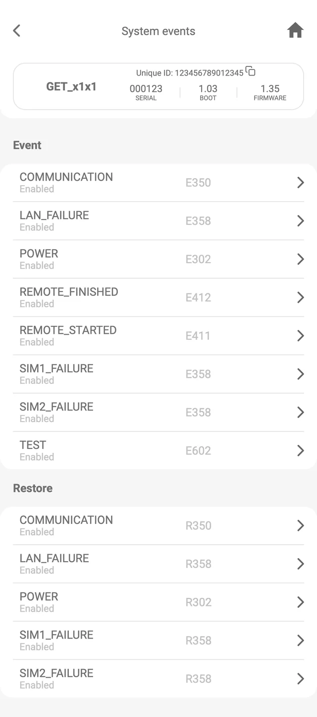
In TrikdisConfig, open the Event summary window.
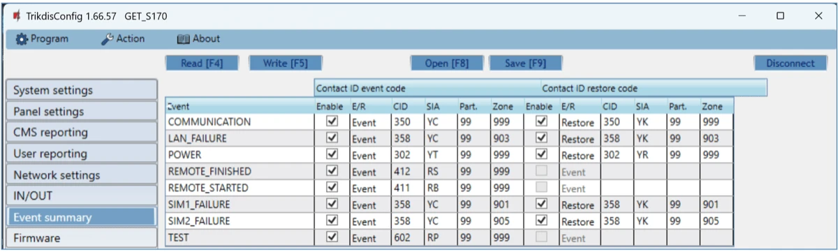
-
COMMUNICATION – message about connection error between the control panel and communicator.
-
LAN_FAILURE - LAN communication failure message.
-
POWER – message about low power supply voltage.
-
REMOTE_FINISHED – message about disconnection from remote configuration with TrikdisConfig.
-
REMOTE_STARTED – message about remote connection to configure GET with TrikdisConfig.
-
SIM1_FAILURE - mobile communication failure message.
-
SIM2_FAILURE - mobile communication failure message.
-
TEST – periodic test message.
Note
To enable periodic TEST messages and set their period, see Test period in Test, ping and reporting mode.
- Enable (Enabled) – when selected, the sending of messages is enabled.
You can change the Contact ID (SIA) code for each event, and also the zone and partition number.
6.9 Restoring factory settings
The Protegus app cannot restore factory settings. Use TrikdisConfig or the RESET button.
To restore the communicator's factory settings, you need to click the “Restore” button in the TrikdisConfig window.

Another way to restore factory settings.
Power supply is connected to the communicator. Press and hold the “RESET” button on the communicator PCB board. Hold the “RESET” button pressed for 10 seconds until the LED indicators ("NETWORK", "POWER", "TROUBLE") turn off and the LED "POWER" indicator lights up. Release the "RESET" button. The communicator's factory settings have been restored.
7. Remote configuration
Important
Remote configuration will work only if:
-
The inserted SIM card is activated and the PIN code is either entered or disabled;
-
Or a LAN cable is connected.
-
"Protegus cloud" is enabled. How to enable cloud is described in section 6.5 "User reporting" window;
-
Power supply is connected ("POWER" LED illuminates green);
-
Registered to the cellular network ("NETWORK LTE" LED illuminates green and blinks yellow).
-
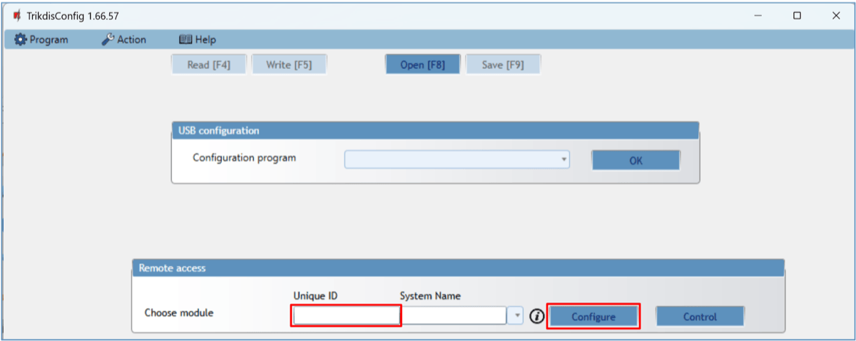
Start the configuration program TrikdisConfig.
-
In the “Remote access” section enter the communicator’s “IMEI/Unique ID” number. This number can be found on the device and the packaging sticker.
-
(Optional) in the “System name” field, enter the desired name for the communicator with this Unique ID.
-
Press “Configure”.
-
In the newly opened window click Read [F4]. If required, enter the administrator or installer code*.* To save the password, select “Remember password”.
-
Set the necessary settings and when finished, click Write [F5].
8. Test communicator performance
When the configuration and installation is complete, perform a system check:
- Generate an event:
-
by arming/disarming the system with the control panel’s keypad;
-
by triggering a zone alarm when the security system is armed.
-
Make sure that the event arrives to the CMS (Central Monitoring Station) and/or is received in the Protegus2 application.
-
To test communicator input, trigger it and make sure to receive the correct event.
-
To test the communicator outputs, activate them remotely and check their operation.
-
If the security control panel will be controlled remotely, arm/disarm the security system remotely by using the Protegus2 app.
9. Firmware update
Note
When the communicator is connected to TrikdisConfig, the program will automatically offer to update the device's firmware if updates are present. Updates require an internet connection. Antivirus software, firewall or strict access to internet settings can block the automatic firmware updates. In this case, you will need to reconfigure your antivirus program.
The communicator’s firmware can also be updated or changed manually. After an update, all previously set settings will remain unchanged. When writing firmware manually, it can be changed to a newer or older version. To update:
-
Run TrikdisConfig.
-
Connect the communicator via USB cable to the computer or connect to the communicator remotely.
- If a newer firmware version exists, the software will offer to download the newer firmware version file.
-
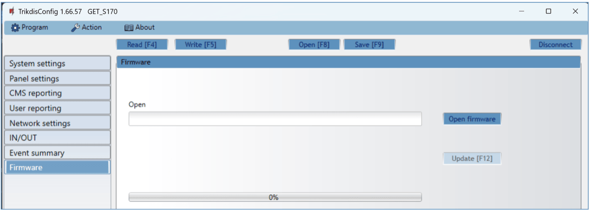
Select the menu branch “Firmware”.
-
Press “Open firmware” and select the required firmware file.
-
Press Update [F12].
-
Wait for the update to complete.
10. Safety requirements
The communicator should be installed and maintained by qualified personnel.
Prior to installation, please read this manual carefully in order to avoid mistakes that can lead to malfunction or even damage to the equipment.
Disconnect the power supply before making any electrical connections.
Changes, modifications or repairs not authorized by the manufacturer shall void your rights under the warranty.
 Please act according to your local rules and do not dispose of your unusable alarm system or its components with other household waste.
11. Annex
The communicator converts Contact ID codes received from the alarm control panel into SIA codes.
Contact ID to SIA code conversion table
| System Event | CID Report Code | SIA Report Code |
|---|---|---|
| Medical alarm | E100 | "MA" |
| Personal emergency | E101 | "QA" |
| Fire in zone: | E110 | "FA" |
| Water flow detected in zone: | E113 | "SA" |
| Pull station alarm in zone: | E115 | "FA" |
| Panic in zone: | E120 | "PA" |
| Panic alarm by user: | E121 | "HA" |
| Panic alarm in zone: | E122 | "PA" |
| Panic alarm in zone: | E123 | "PA" |
| Panic alarm in zone: | E124 | "HA" |
| Panic alarm in zone: | E125 | "HA" |
| Alarm active in zone: | E130 | "BA" |
| Alarm active in zone: | E131 | "BA" |
| Alarm active in zone: | E132 | "BA" |
| Alarm active in zone: | E133 | "BA" |
| Alarm active in zone: | E134 | "BA" |
| Alarm active in zone: | E135 | "BA" |
| Tamper active in zone: | E137 | "TA" |
| Intrusion verified in zone: | E139 | "BV" |
| Alarm active in zone: | E140 | "UA" |
| System failure (143) | E143 | "ET" |
| Tamper active in zone: | E144 | "TA" |
| Tamper active in zone: | E145 | "TA" |
| Alarm active in zone: | E146 | "BA" |
| Alarm active in zone: | E150 | "UA" |
| Gas detected in zone: | E151 | "GA" |
| Water leakage detected in zone: | E154 | "WA" |
| Foil break detected in zone: | E155 | "BA" |
| High temperature at sensor: | E158 | "KA" |
| Low temperature at sensor: | E159 | "ZA" |
| CO detected in zone: | E162 | "GA" |
| Fire failure in zone: | E200 | "FS" |
| Monitored alarm | E220 | "BA" |
| System failure (300) | E300 | "YP" |
| AC power supply loss | E301 | "AT" |
| Low battery | E302 | "YT" |
| System failure (304) | E304 | "YF" |
| System reset in zone: | E305 | "RR" |
| Panel programming changed | E306 | "YG" |
| System shutdown | E308 | "RR" |
| Battery failure (309) | E309 | "YT" |
| Ground fault | E310 | "US" |
| Battery failure (311) | E311 | "YM" |
| Power supply overcurrent (312) | E312 | "YP" |
| Engineer reset by user: | E313 | "RR" |
| Sounder/Relay failure | E320 | "RC" |
| System failure (321) | E321 | "YA" |
| System failure (330) | E330 | "ET" |
| System failure (332) | E332 | "ET" |
| System failure (333) | E333 | "ET" |
| System failure (336) | E336 | "VT" |
| System failure (338) | E338 | "ET" |
| System failure (341) | E341 | "ET" |
| System failure (342) | E342 | "ET" |
| System failure (343) | E343 | "ET" |
| System failure (344) | E344 | "XQ" |
| System communication failure (350) | E350 | "YC" |
| System communication failure (351) | E351 | "LT" |
| System communication failure (352) | E352 | "LT" |
| System failure (353) | E353 | "YC" |
| System communication failure (354) | E354 | "YC" |
| System failure (355) | E355 | "UT" |
| Fire trouble in zone: | E373 | "FT" |
| Trouble in zone: | E374 | "EE" |
| Trouble in zone: | E378 | "BG" |
| Trouble in zone: | E380 | "UT" |
| Wireless zone fault: | E381 | "US" |
| Wireless module failure (382) | E382 | "UY" |
| Tamper active in zone: | E383 | "TA" |
| Low battery in wireless zone: | E384 | "XT" |
| Trouble in zone: | E389 | "ET" |
| Trouble in zone: | E391 | "NA" |
| Trouble in zone: | E393 | "NC" |
| User | E400 | "OP" |
| User | E401 | "OP" |
| Automatic disarm | E403 | "OA" |
| Deferred disarm | E405 | "OR" |
| Alarm cancelled by user: | E406 | "BC" |
| User | E407 | "OP" |
| Quick disarm | E408 | "OP" |
| Remote disarm | E409 | "OS" |
| Call back request made by CMS | E411 | "RB" |
| Successful data download | E412 | "RS" |
| Entry access denied for user | E421 | "JA" |
| Entry by user | E422 | "DG" |
| Forced Access | E423 | "DF" |
| Exit access denied for user | E424 | "DD" |
| Exit by user | E425 | "DR" |
| User | E451 | "OK" |
| User | E452 | "OJ" |
| User | E453 | "CT" |
| User | E454 | "CI" |
| Auto arm failed | E455 | "CI" |
| Partial arm by user: | E456 | "CG" |
| Exit violation by user: | E457 | "EE" |
| System disarmed after alarm by user: | E458 | "OR" |
| Recent arm | E459 | "CR" |
| Wrong code entered | E461 | "JA" |
| Auto-arm time extended by user: | E464 | "CE" |
| Device disabled (501) | E501 | "RL" |
| Device disabled (520) | E520 | "RO" |
| Wireless sensor disabled in zone: | E552 | "YS" |
| Zone | E570 | "UB" |
| Zone | E571 | "FB" |
| Zone | E572 | "MB" |
| Zone | E573 | "BB" |
| Group bypass by user: | E574 | "CG" |
| Zone | E576 | "UB" |
| Zone | E577 | "UB" |
| Vent zone bypass | E579 | "UB" |
| Walk test activated by user: | E607 | "TS" |
| Manual test report | E601 | "RX" |
| Periodic test report | E602 | "RP" |
| System event (605) | E605 | "JL" |
| System event (606) | E606 | "LF" |
| Periodic test report with trouble | E608 | "RY" |
| System event (622) | E622 | "JL" |
| System event (623) | E623 | "JL" |
| Time/Date was reset by user | E625 | "JT" |
| Inaccurate Time/Date | E626 | "JT" |
| System programming started | E627 | "LB" |
| System programming finished | E628 | "LS" |
| System event (631) | E631 | "JS" |
| System event (632) | E632 | "JS" |
| System not active (654) | E654 | "CD" |
| Medical alarm restored | R100 | "MH" |
| Personal emergency restored | R101 | "QH" |
| No more fire alarm in zone : | R110 | "FH" |
| No more water flow alarm in zone: | R113 | "SH" |
| Panic alarm restored in zone: | R120 | "PH" |
| Panic alarm cancelled by user: | R121 | "HH" |
| Panic alarm restored in zone: | R122 | "PH" |
| Panic alarm restored in zone: | R123 | "PH" |
| Panic alarm restored in zone: | R124 | "HH" |
| Panic alarm restored in zone: | R125 | "HH" |
| No more alarm in zone: | R130 | "BH" |
| No more alarm in zone: | R131 | "BH" |
| No more alarm in zone: | R132 | "BH" |
| No more alarm in zone: | R133 | "BH" |
| No more alarm in zone: | R134 | "BH" |
| No more alarm in zone: | R135 | "BH" |
| No more tamper in zone: | R137 | "TA" |
| No more alarm in zone: | R140 | "UH" |
| No more system failure (143) | R143 | "ER" |
| No more tamper in zone: | R144 | "TR" |
| No more tamper in zone: | R145 | "TR" |
| No more alarm in zone: | R146 | "BH" |
| No more alarm in zone: | R150 | "UH" |
| No more gas alarm in zone: | R151 | "GH" |
| No more water leakage alarm in zone: | R154 | "WH" |
| Foil break restored in zone: | R155 | "BH" |
| Temperature has normalized at sensor: | R158 | "KH" |
| Temperature has normalized at sensor: | R159 | "ZH" |
| No more CO alarm in zone: | R162 | "GH" |
| No more fire failure in zone: | R200 | "FV" |
| Monitored restore alarm | R220 | "BH" |
| No more system failure (300) | R300 | "YQ" |
| AC power supply OK | R301 | "AR" |
| Battery OK | R302 | "YR" |
| No more system failure (304) | R304 | "YG" |
| System reset restored in zone: | R305 | "RR" |
| No more battery failure (309) | R309 | "YR" |
| Restore ground fault | R310 | "UR" |
| No more battery failure (311) | R311 | "YR" |
| Restore power supply overcurrent (312) | R312 | "YQ" |
| No more sounder/Relay failure | R320 | "RO" |
| No more system failure (321) | R321 | "YH" |
| No more system failure (330) | R330 | "ER" |
| No more system failure (332) | R332 | "ER" |
| No more system failure (333) | R333 | "ER" |
| No more system failure (336) | R336 | "VR" |
| No more system failure (338) | R338 | "ER" |
| No more system failure (341) | R341 | "ER" |
| No more system failure (342) | R342 | "ER" |
| No more system failure (344) | R344 | "XH" |
| No more system communication failure (350) | R350 | "YK" |
| No more system communication failure (351) | R351 | "LR" |
| No more system communication failure (352) | R352 | "LR" |
| No more system failure (353) | R353 | "YK" |
| No more system communication failure (354) | R354 | "YK" |
| No more system failure (355) | R355 | "UJ" |
| Fire trouble restored in zone: | R373 | "FJ" |
| No more trouble in zone: | R374 | "EA" |
| No more trouble in zone: | R380 | "UJ" |
| No more wireless zone fault: | R381 | "UR" |
| No more wireless module failure (382) | R382 | "BR" |
| No more tamper in zone: | R383 | "TR" |
| Battery OK in wireless zone: | R384 | "XR" |
| No more trouble in zone: | R391 | "NS" |
| No more trouble in zone: | R393 | "NS" |
| User | R400 | "CL" |
| User | R401 | "CL" |
| Automatic arm | R403 | "CA" |
| User | R407 | "CL" |
| Quick arm | R408 | "CL" |
| Remote arm | R409 | “CS” |
| User | R441 | "CG" |
| User | R451 | “CK” |
| User | R452 | “CJ” |
| User | R454 | “CI” |
| Partial Arm by user: | R456 | "CG" |
| Recent disarm | R459 | “CR” |
| Device enabled (501) | R501 | "RG" |
| Device enabled (520) | R520 | "RC" |
| Wireless sensor enabled in zone: | R552 | "YK" |
| Zone | R570 | "UU" |
| Zone | R571 | "FU" |
| Zone | R572 | "MU" |
| Zone | R573 | "BU" |
| Group bypass by user: | R574 | "CF" |
| Zone | R576 | "UU" |
| Zone | R577 | "UU" |
| Vent zone bypass cancelled | R579 | "UU" |
| Walk test deactivated by user | R607 | "TE" |
| Time/Date was reset by user | R625 | "JT" |
| System active (654) | R654 | "CD" |