Interlogix NX-8v2 with E16 quick setup
Short steps to connect the E16 communicator to Interlogix NX-8v2 panels, configure E16 for IP reporting, and add the system to Protegus2. Use this together with the full E16 manual for all other settings.
Caution
Install and service only by qualified personnel. Disconnect power before wiring. Unauthorized changes void warranty.
1. Prerequisites
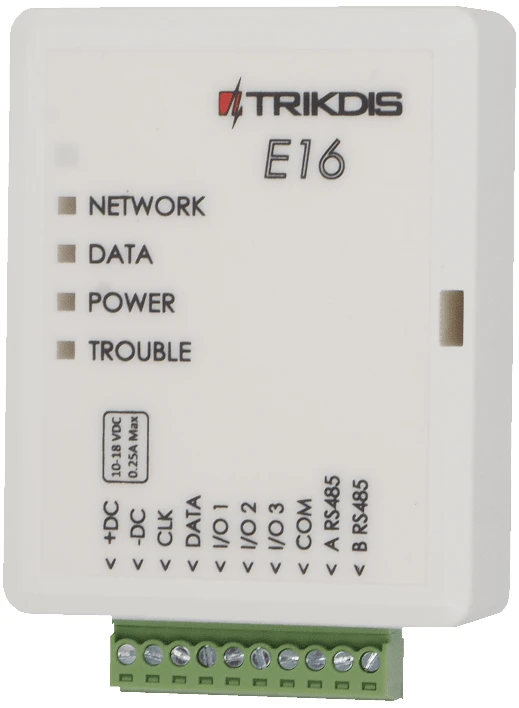
- E16 communicator with LAN connected and a USB Mini-B cable available for configuration.
- Interlogix NX-8v2 panel with keypad access.
- CMS object ID / account number if reporting to CMS.
- Protegus2 account and communicator MAC / Unique ID.
2. Quick configuration with TrikdisConfig software
- Download TrikdisConfig from www.trikdis.com and install it.
- Open the E16 casing with a flat-head screwdriver.
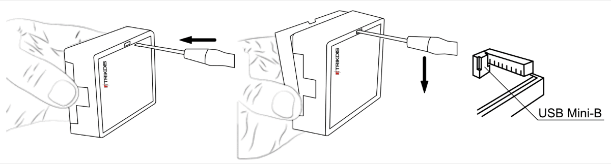
- Connect E16 to the computer with a USB Mini-B cable.
- Run TrikdisConfig. The software will recognize the communicator and open the configuration window.
- Click Read [F4] to load the current settings. If requested, enter the Administrator or Installer 6-digit code.
Complete the subsection that matches the installation:
- Protegus2 app if the system will be controlled remotely by users.
- Central Monitoring Station if the communicator will report to CMS.
- Complete both subsections if the communicator must support both CMS and Protegus2.
2.1 Settings for connection with Protegus2 app
In "System settings" window:
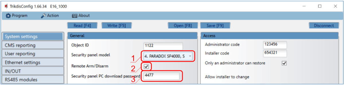
- Select the Security panel model that will be connected to the communicator.
- Select Remote Arm/Disarm if users must control the panel in Protegus2 with their keypad code.
- For direct control of Paradox and Texecom panels, enter the Security panel PC download password. It must match the password set in the control panel.
Note
For direct control to work, the control panel must also be programmed as described in the panel-specific section below.
In "User reporting" window, "PROTEGUS Cloud" tab:
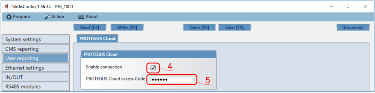
- Tick Enable connection to the Protegus Cloud.
- Change the Protegus Cloud access Code if users should be asked to enter it when adding the system to Protegus2.
After finishing configuration, click Write [F5] and disconnect the USB cable.
2.2 Settings for connection with Central Monitoring Station
In "System settings" window:
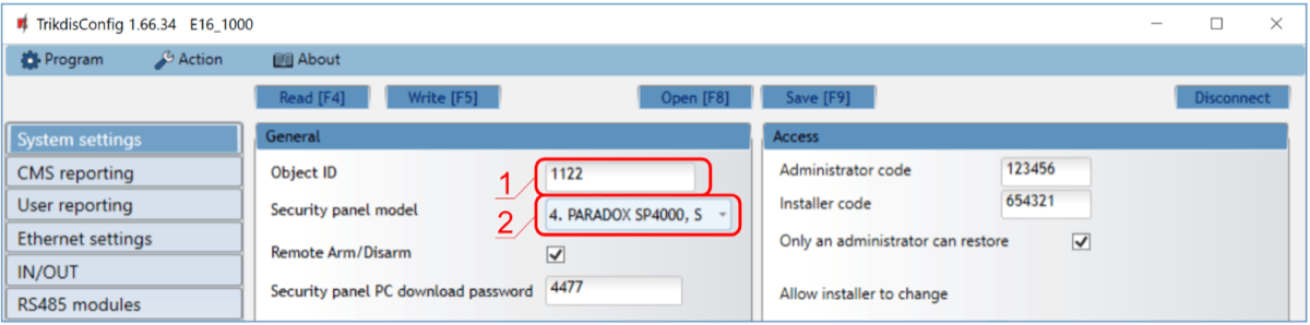
- Enter the Object ID provided by the Central Monitoring Station.
- Select the Security panel model that will be connected to the communicator.
In "CMS reporting" window settings for "Primary channel":
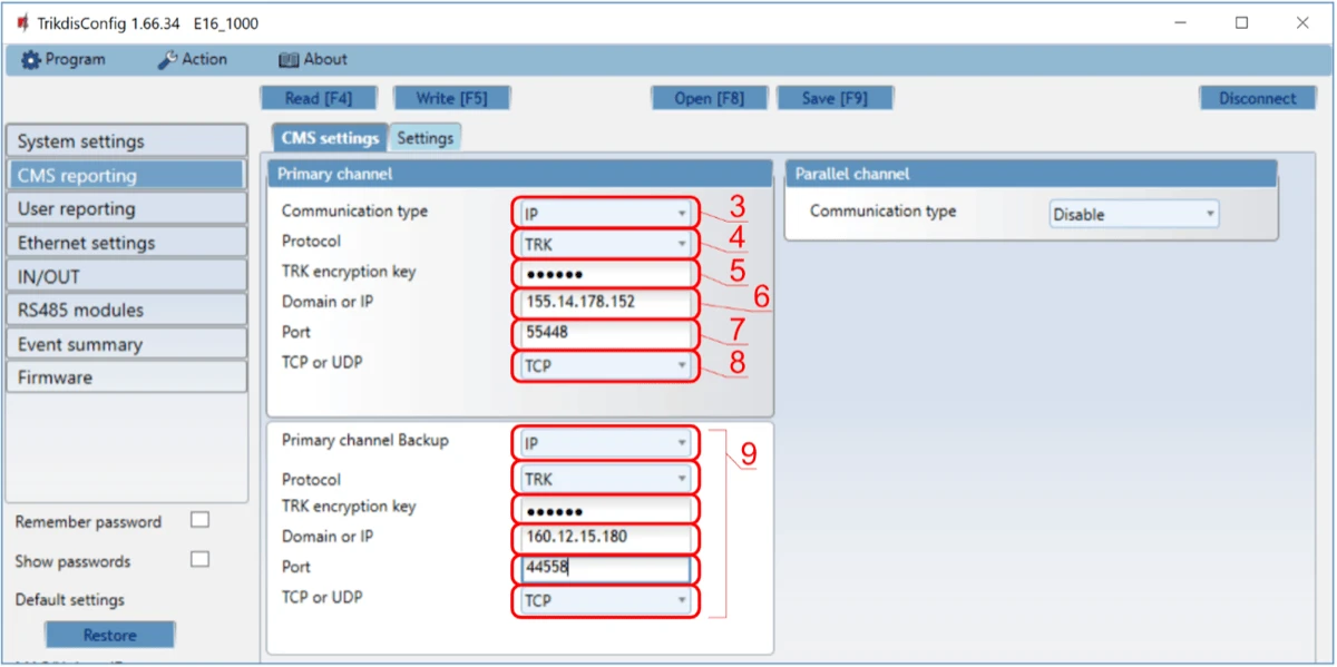
- Set Communication type to IP.
- Select the protocol required by the receiver: TRK, DC-09_2007, DC-09_2012, or TL150.
- Enter the receiver encryption key if the selected protocol requires it.
- Enter the receiver Domain or IP and Port.
- Select TCP or UDP.
- Configure backup and parallel channels if the installation requires redundancy.
Note
If you select a DC-09 protocol, also enter the object, line, and receiver numbers in the Settings tab of the CMS reporting window.
After finishing configuration, click Write [F5] and disconnect the USB cable.
3. Wiring
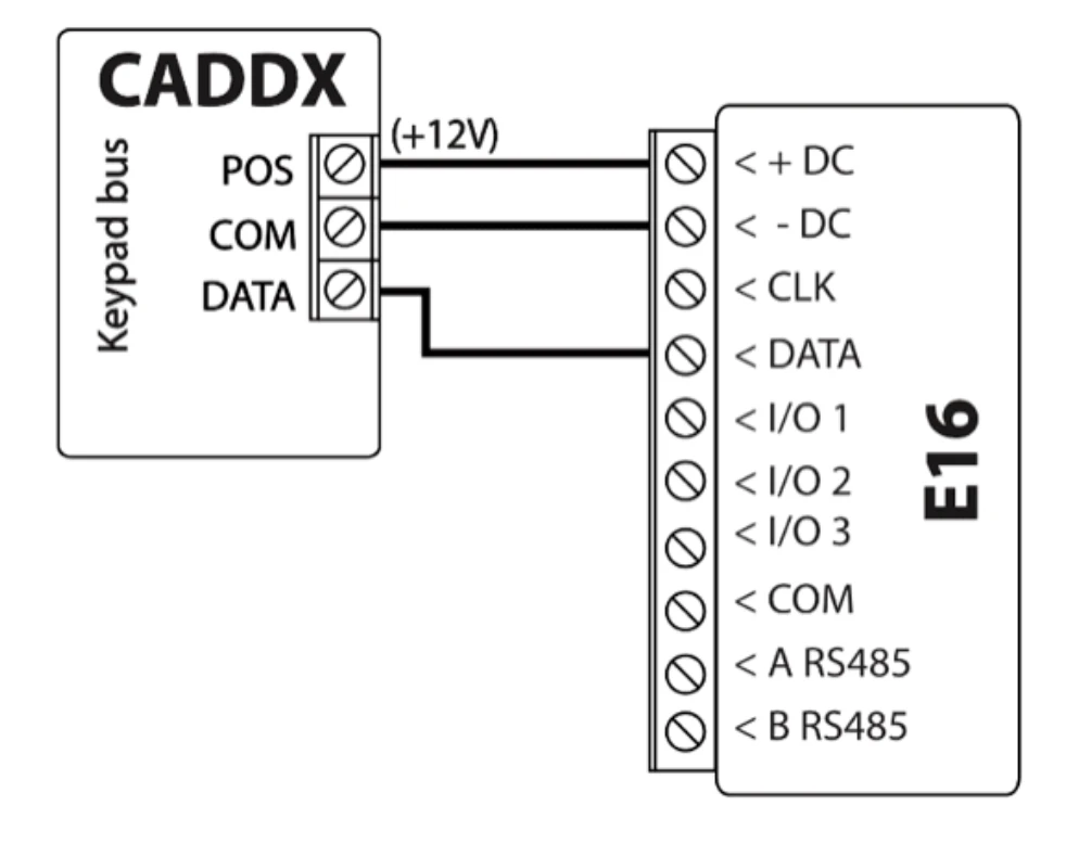
Connect the panel to E16 as shown below:
| E16 terminal | Interlogix panel | Notes |
|---|---|---|
+DC | POS | Panel power |
-DC | COM | Panel ground |
DATA | DATA | Keypad bus data |
4. Panel programming via LCD keypad
Using the control panel keypad, enter these sections and set them as described:
| LCD keypad | Keypad entry | Action description |
|---|---|---|
| System ready | *89713 | Enter programming mode |
| Enter device address | 0# | Go to the main panel programming menu |
| Enter location | 4# | Go to Phone1 events reported |
| Loc#4 Seg#1 | 12345678* | Enable all toggle options, then save |
| Loc#4 Seg#2 | 12345678* | Enable all toggle options, then save |
| Enter location | 23# | Go to Partition features |
| Loc#23 Seg#1 | ** | Move to segment 3 |
| Loc#23 Seg#3 | 12345678*# | Enable all toggle options, then save |
| Enter location | 37# | Go to Siren and system supervision |
| Loc#37 Seg#1 | ** | Move to segment 3 |
| Loc#37 Seg#3 | 12345678* | Enable all toggle options, then save |
| Loc#37 Seg#4 | 12345678*# | Enable all toggle options, then save |
| Enter location | 90# | Go to Partition 2 features |
| Loc#90 Seg#1 | ** | Move to segment 3 |
| Loc#90 Seg#3 | 12345678*# | Enable all toggle options, then save |
| Enter location | 93# | Go to Partition 3 features |
| Loc#93 Seg#1 | ** | Move to segment 3 |
| Loc#93 Seg#3 | 12345678*# | Enable all toggle options, then save |
| Enter location | 96# | Go to Partition 4 features |
| Loc#96 Seg#1 | ** | Move to segment 3 |
| Loc#96 Seg#3 | 12345678*# | Enable all toggle options, then save |
| Enter location | 99# | Go to Partition 5 features |
| Loc#99 Seg#1 | ** | Move to segment 3 |
| Loc#99 Seg#3 | 12345678*# | Enable all toggle options, then save |
| Enter location | 102# | Go to Partition 6 features |
| Loc#102 Seg#1 | ** | Move to segment 3 |
| Loc#102 Seg#3 | 12345678*# | Enable all toggle options, then save |
| Enter location | 105# | Go to Partition 7 features |
| Loc#105 Seg#1 | ** | Move to segment 3 |
| Loc#105 Seg#3 | 12345678*# | Enable all toggle options, then save |
| Enter location | 108# | Go to Partition 8 features |
| Loc#108 Seg#1 | ** | Move to segment 3 |
| Loc#108 Seg#3 | 12345678*# | Enable all toggle options, then save |
| Enter location | EXIT EXIT | Exit programming mode |
5. Panel programming via LED keypad
Use the same locations and values as above:
| LED keypad state | Keypad entry | Action description |
|---|---|---|
| Ready and Power LEDs on | *89713 | Enter programming mode |
| Service LED blinks | 0# | Go to the main panel programming menu |
| Service LED blinks, Armed LED on | 4# | Go to Phone1 events reported |
| All zone LEDs on | 12345678* | Enable all toggle options, then save |
| All zone LEDs on | 12345678* | Enable all toggle options, then save |
| Service LED blinks, Armed LED on | 23# | Go to Partition features |
| Service LED blinks, Ready LED on | ** | Move to segment 3 |
| Service LED blinks, Ready LED on | 12345678*# | Enable all toggle options, then save |
| Service LED blinks, Armed LED on | 37# | Go to Siren and system supervision |
| Service LED blinks, Ready LED on | ** | Move to segment 3 |
| Service LED blinks, Ready LED on | 12345678* | Enable all toggle options, then save |
| Service LED blinks, Ready LED on | 12345678*# | Enable all toggle options, then save |
| Service LED blinks, Armed LED on | 90# | Go to Partition 2 features |
| Service LED blinks, Ready LED on | ** | Move to segment 3 |
| Service LED blinks, Ready LED on | 12345678*# | Enable all toggle options, then save |
| Service LED blinks, Armed LED on | 93# | Go to Partition 3 features |
| Service LED blinks, Ready LED on | ** | Move to segment 3 |
| Service LED blinks, Ready LED on | 12345678*# | Enable all toggle options, then save |
| Service LED blinks, Armed LED on | 96# | Go to Partition 4 features |
| Service LED blinks, Ready LED on | ** | Move to segment 3 |
| Service LED blinks, Ready LED on | 12345678*# | Enable all toggle options, then save |
| Service LED blinks, Armed LED on | 99# | Go to Partition 5 features |
| Service LED blinks, Ready LED on | ** | Move to segment 3 |
| Service LED blinks, Ready LED on | 12345678*# | Enable all toggle options, then save |
| Service LED blinks, Armed LED on | 102# | Go to Partition 6 features |
| Service LED blinks, Ready LED on | ** | Move to segment 3 |
| Service LED blinks, Ready LED on | 12345678*# | Enable all toggle options, then save |
| Service LED blinks, Armed LED on | 105# | Go to Partition 7 features |
| Service LED blinks, Ready LED on | ** | Move to segment 3 |
| Service LED blinks, Ready LED on | 12345678*# | Enable all toggle options, then save |
| Service LED blinks, Armed LED on | 108# | Go to Partition 8 features |
| Service LED blinks, Ready LED on | ** | Move to segment 3 |
| Service LED blinks, Ready LED on | 12345678*# | Enable all toggle options, then save |
| Service LED blinks, Armed LED on | EXIT EXIT | Exit programming mode |
6. Add system to Protegus2
- Open Protegus2 and click Add new system.
- Enter the E16 MAC / Unique ID.
- Enter the system name and finish the wizard.
- If you use keyswitch control instead of direct control, connect
I/O 1to the panel keyswitch zone and configurePGM1in Protegus2. - Wait until the system shows as online.
7. System check
- Arm and disarm the system from the keypad.
- Trigger a test alarm while the system is armed.
- Confirm that events reach the CMS and Protegus2.