E16T quick setup
Short steps to connect the E16T communicator to a control panel telephone dialer, configure IP reporting, and add the system to Protegus. Use this together with the full E16T manual for all other settings.
Caution
Install and service only by qualified personnel. Disconnect power before wiring. Unauthorized changes void warranty.
1. Prerequisites
- E16T communicator with LAN connected and a USB Mini-B cable available for configuration.
- Control panel with a telephone communicator that supports Contact ID over DTMF tones.
- Panel installer / keypad access.
- CMS account number if reporting to CMS.
- Protegus account and communicator MAC / Unique ID.
2. Quick configuration with TrikdisConfig software
- Download TrikdisConfig from www.trikdis.com and install it.
- Open the E16T casing with a flat-head screwdriver.
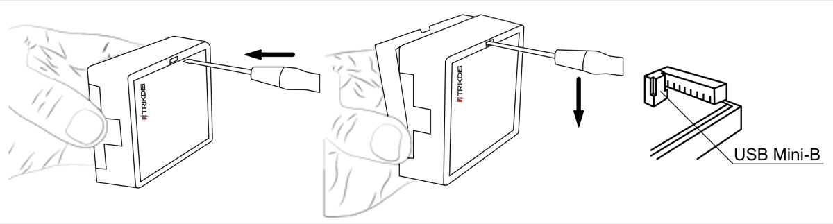
- Connect E16T to the computer with a USB Mini-B cable.
- Run TrikdisConfig. The software will recognize the communicator and open the configuration window.
- Click Read [F4] to load the current settings. If requested, enter the Administrator or Installer 6-digit code.
Complete the subsection that matches the installation:
- Protegus app if users will control the system remotely.
- Central Monitoring Station if the communicator will report to CMS.
- Complete both subsections if the communicator must support both CMS and Protegus.
2.1 Settings for connection with Protegus app
In "System settings" window:
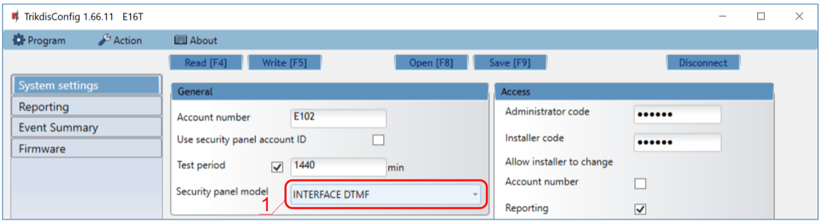
- Select the Security panel model that will be connected to the communicator.
In "Reporting" window, "Protegus Service" tab:
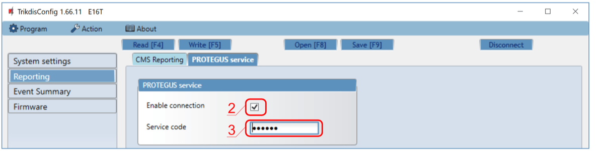
- Tick Enable connection in the Protegus service settings.
- Change the Service code if users should be asked to enter it when adding the system to Protegus.
After finishing configuration, click Write [F5] and disconnect the USB cable.
2.2 Settings for connection with Central Monitoring Station
In "System settings" window:
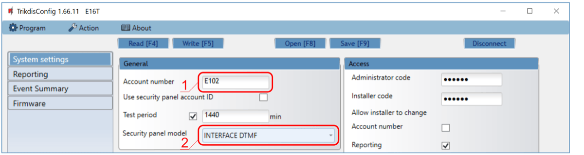
- Enter the Account number provided by the Central Monitoring Station.
- Select the Security panel model that will be connected to the communicator.
In "Reporting" window settings for "Primary" channel:
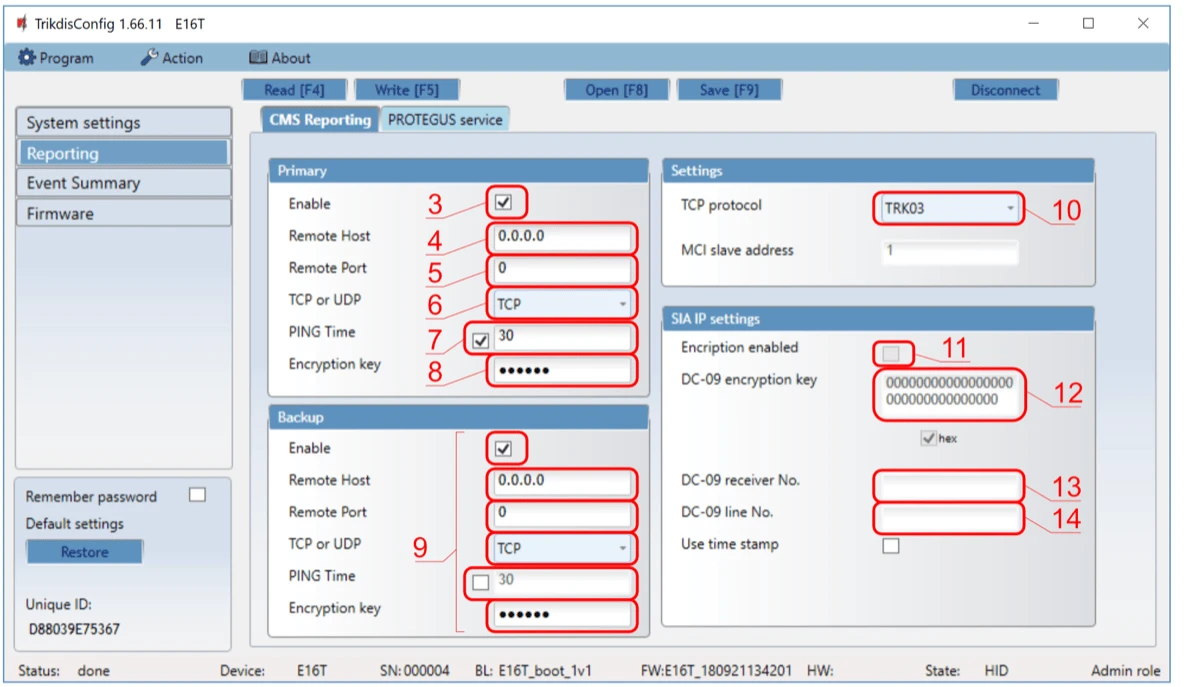
- Enable the primary communication channel.
- Enter the receiver Remote Host and Remote Port.
- Select TCP or UDP.
- Set PING Time and the encryption key required by the receiver.
- Configure Backup settings if the installation requires redundancy.
- Select the TCP protocol required by the receiver: TRK, DC-09_2007, or DC-09_2012.
- If DC-09_2012 is used, configure encryption and the receiver and line numbers.
In "Reporting" window, "Protegus Service" tab:

- Tick Enable connection to Protegus if users will use the app.
- Change the Service code if users should be asked to enter it when adding the system to Protegus.
Note
If you select a DC-09 protocol, also enter the object, line, and receiver numbers in the Settings tab of the Reporting window.
After finishing configuration, click Write [F5] and disconnect the USB cable.
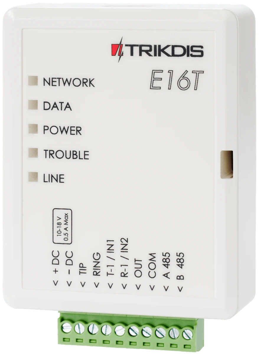
3. Wiring
Connect E16T to panel power, TIP / RING, and LAN as shown below:
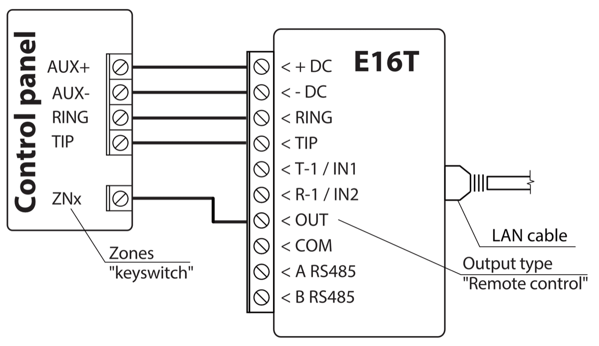
If the panel will be armed or disarmed by keyswitch output control, wire the panel keyswitch zone to OUT as shown in the same diagram.
4. Panel programming
Program the control panel telephone communicator as follows:
- Enable the panel telephone communicator.
- If E16T is connected directly to
TIP/RING, enter any telephone number with at least 2 digits. - Select
DTMFdialing mode. - Select the
Contact IDcommunication protocol. - Enter the panel 4-digit account number.
5. Special settings for Honeywell Vista 48
If the connected panel is Honeywell Vista 48, set these values:
| Section | Data | Section | Data | Section | Data |
|---|---|---|---|---|---|
*41 | 1111 | *60 | 1 | *69 | 1 |
*42 | 1111 | *61 | 1 | *70 | 1 |
*43 | 1234 | *62 | 1 | *71 | 1 |
*44 | 1234 | *63 | 1 | *72 | 1 |
*45 | 1111 | *64 | 1 | *73 | 1 |
*47 | 1 | *65 | 1 | *74 | 1 |
*48 | 7 | *66 | 1 | *75 | 1 |
*50 | 1 | *67 | 1 | *76 | 1 |
*59 | 0 | *68 | 1 |
Exit programming mode with *99.
6. Add system to Protegus
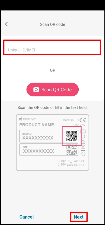
- Open Protegus and click Add new system.
- Enter the E16T MAC / Unique ID.
- Enter the system name and finish the wizard.
- If you wired
OUTto a keyswitch zone, open Settings in Protegus and enable Arm/Disarm with PGM Output 1. - Select Pulse or Level mode to match the panel keyswitch zone type.
7. System check
- Arm and disarm the system from the keypad.
- Trigger a test alarm while the system is armed.
- Confirm that events reach the CMS and Protegus.