Adding S8/S9 wireless sensors to FLEXi SP3
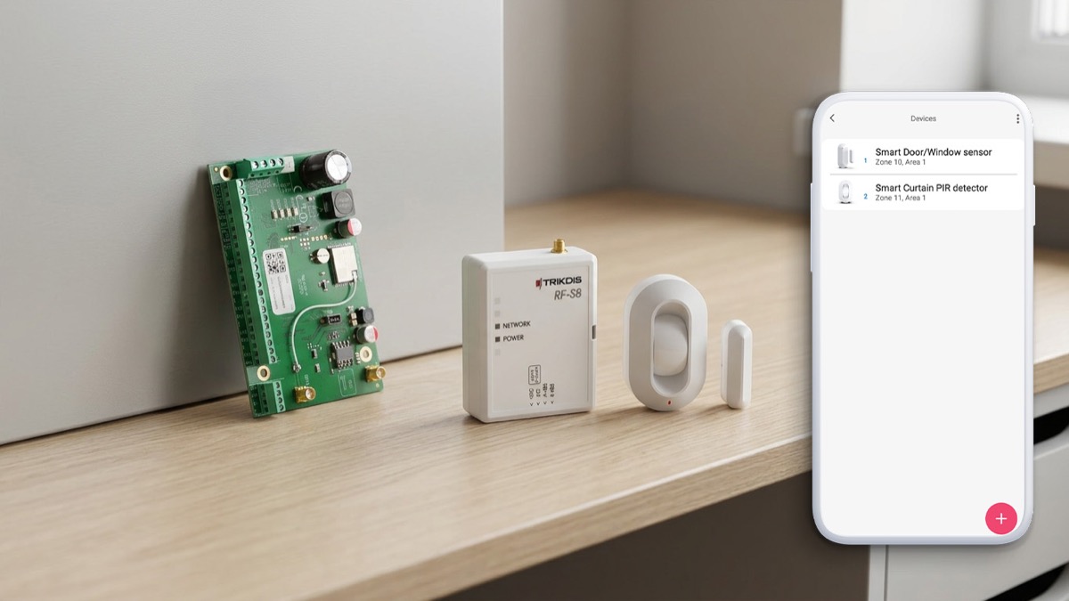
Pair S8 wireless sensors (PIR detectors, door/window magnets, smoke detectors, sirens, remote controls) with the FLEXi SP3 control panel. Choose your configuration method.
Important
Firmware requirement: The FLEXi SP3 must run firmware revision 4 (SP3_xxx4_0122.fw, version 1.22 or later) to support S8 wireless sensors.
Note
Hardware prerequisite: Before pairing sensors, the RF-S8 transceiver must be wired to the SP3's RS485 bus — see 3.13 Schematic for connecting RF-S8 — and registered in TrikdisConfig under the Modules tab — see 5.5 "Modules" window.
Before you start — prepare the sensors (applies to all methods):
- If a sensor was previously paired with any panel, unenroll it first: hold the sensor's learn button for 5 seconds, release when the indicator flashes green three times.
- Insert batteries into all sensors you intend to pair.
- Keep the RF-S8 transceiver at least 1 m away from sensors during pairing.
The Protegus app must be installed on your phone and the SP3 system already added to your account.
-
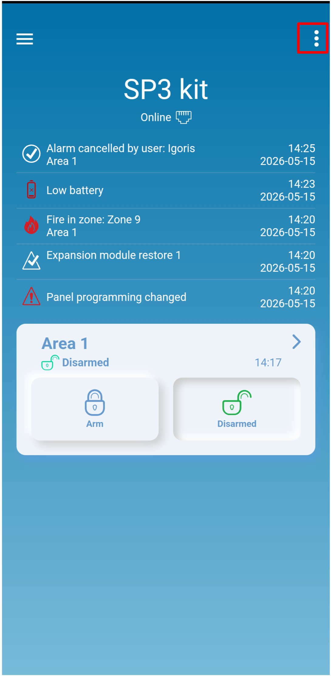
Open the Protegus app and select the SP3 kit system. Tap ⋮ in the top-right corner.
-
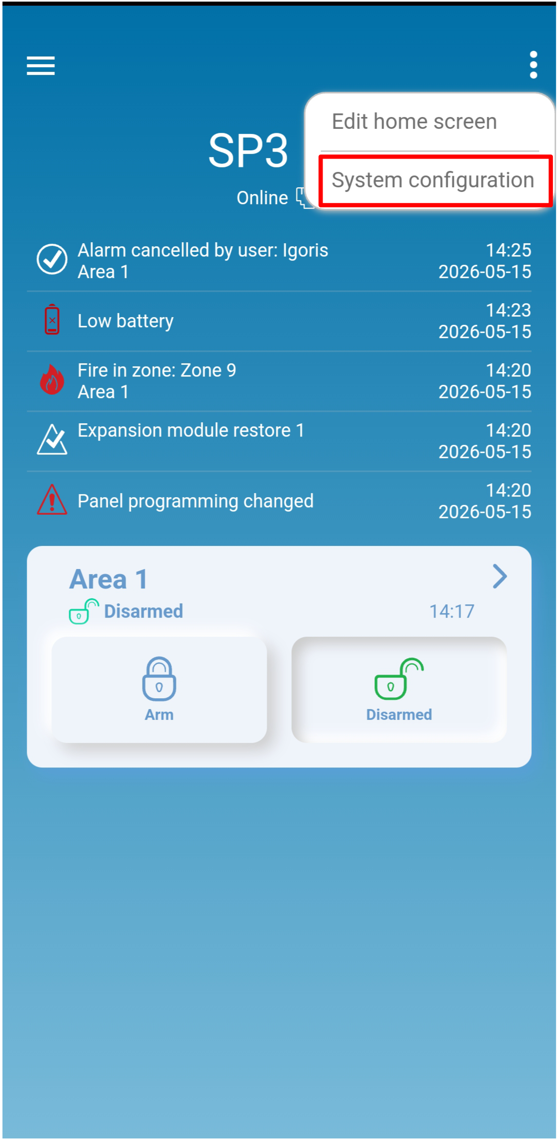
Tap System configuration.
-
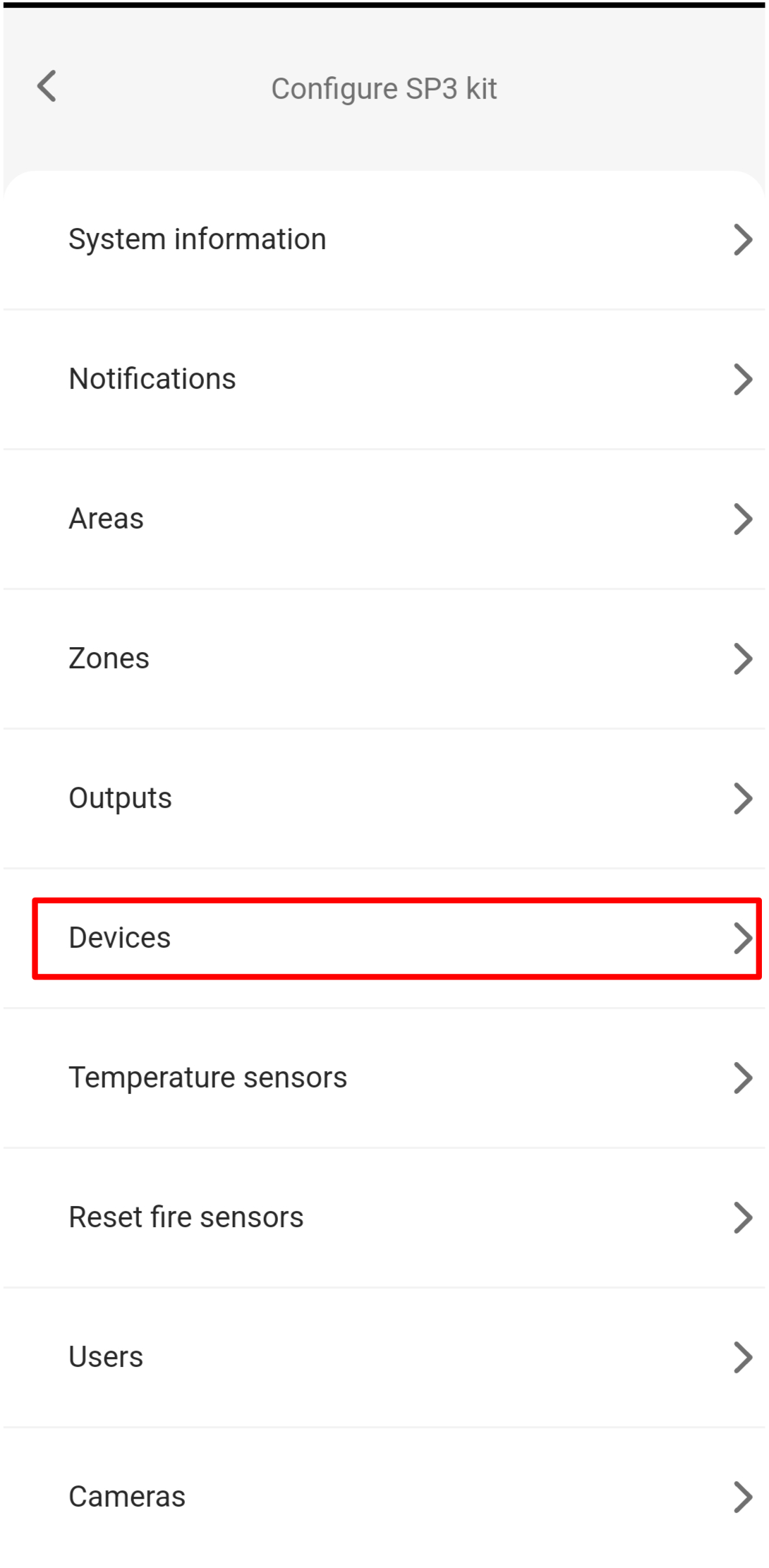
Tap Devices.
-
Tap the + button to add a new sensor.
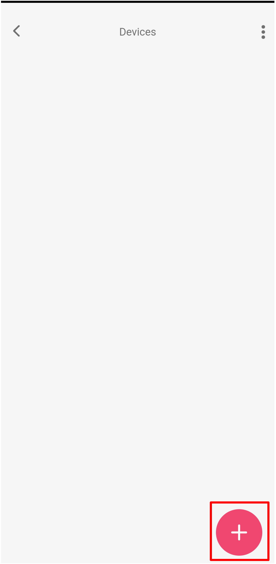
-
Select the sensor type you want to pair (e.g. Smart PET PIR detector).
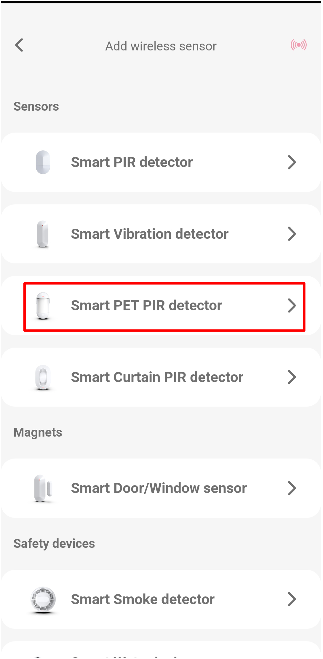
-
The app shows the sensor in Learning mode with a diagram of the learn button. Press and hold the learn button until the green indicator stays lit for 2 seconds.
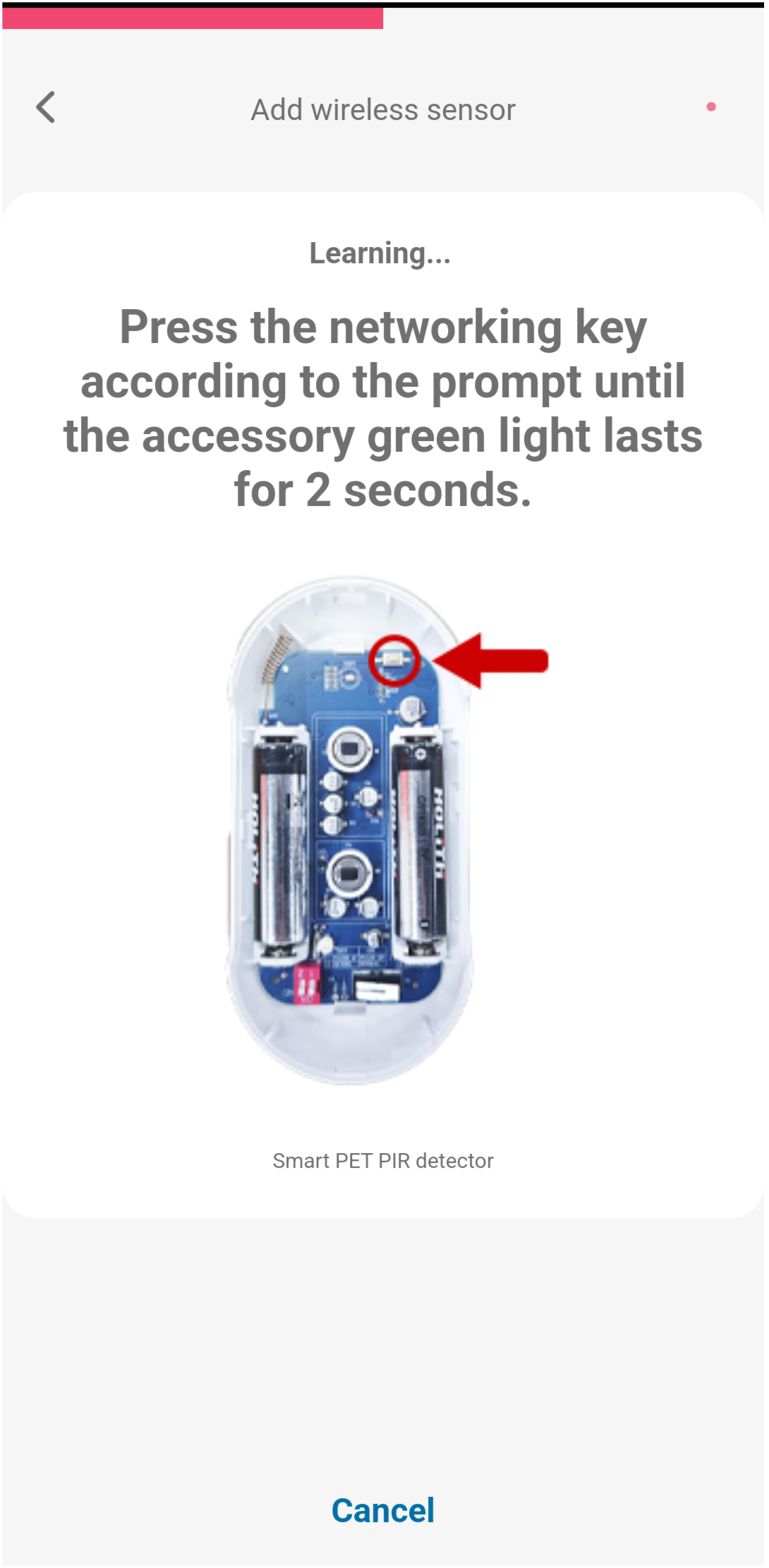
-
When the sensor is detected, a confirmation appears with its serial number. Tap OK.
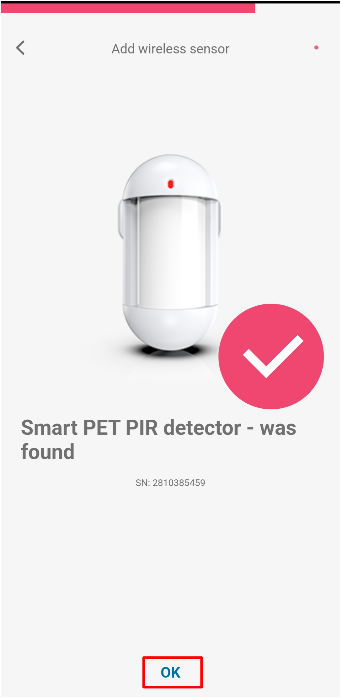
-
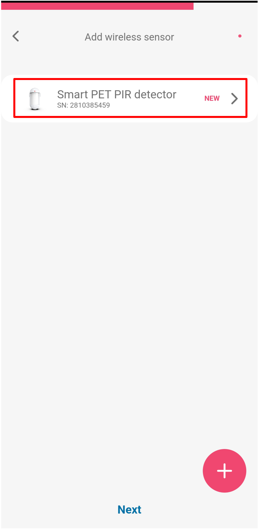
The sensor appears in the list with a NEW badge. Tap the sensor to open its settings.
Configure zone settings:
-
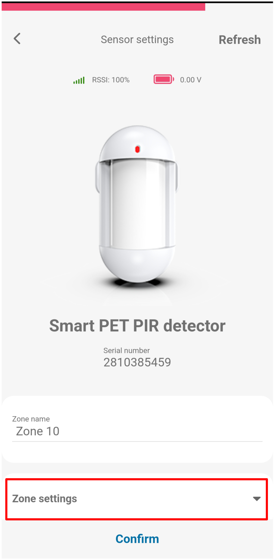
Tap Zone settings to expand the section.
-
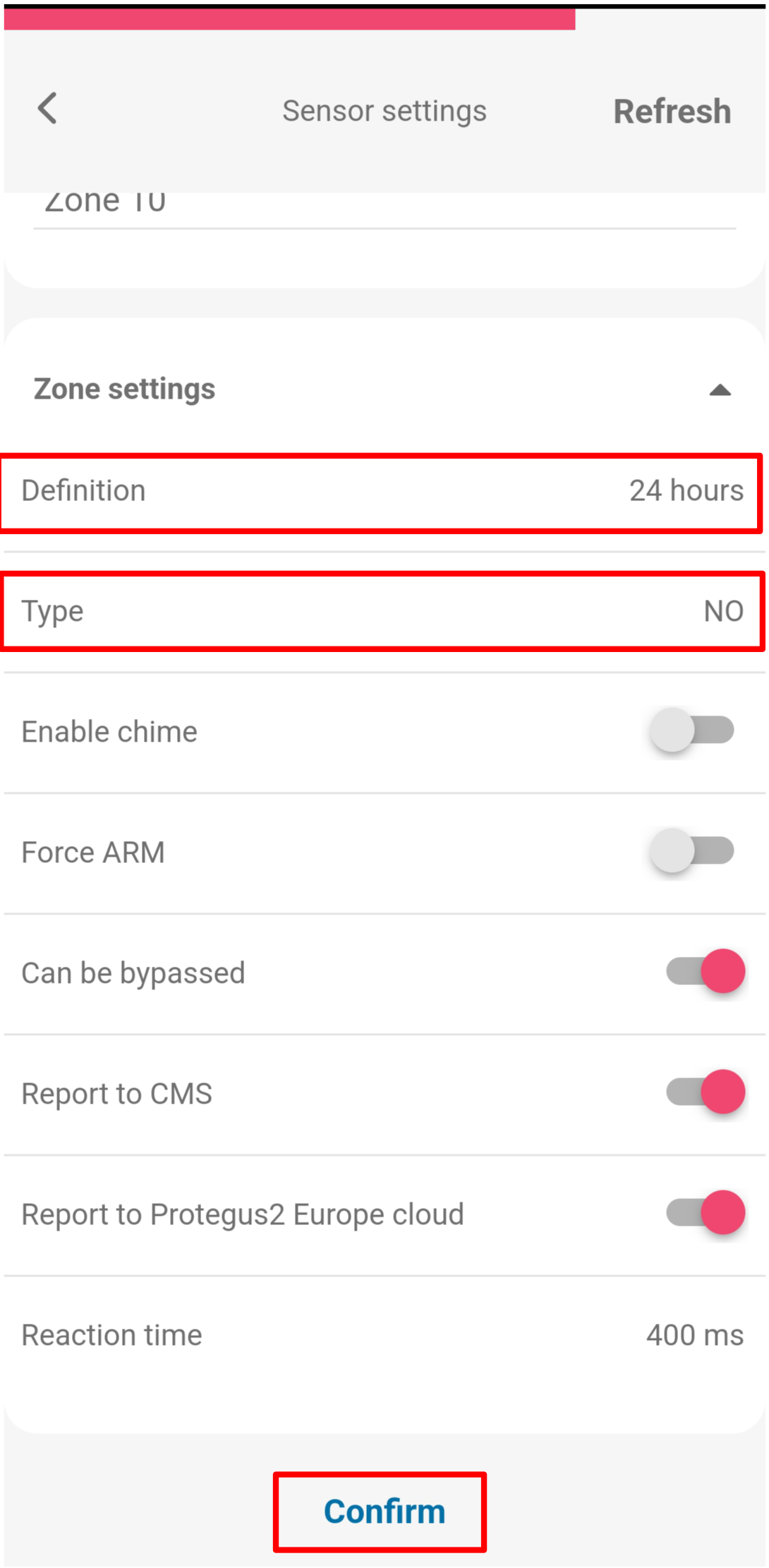
Set the Definition (e.g. 24 hours) and Type (e.g. NO), then tap Confirm.
-
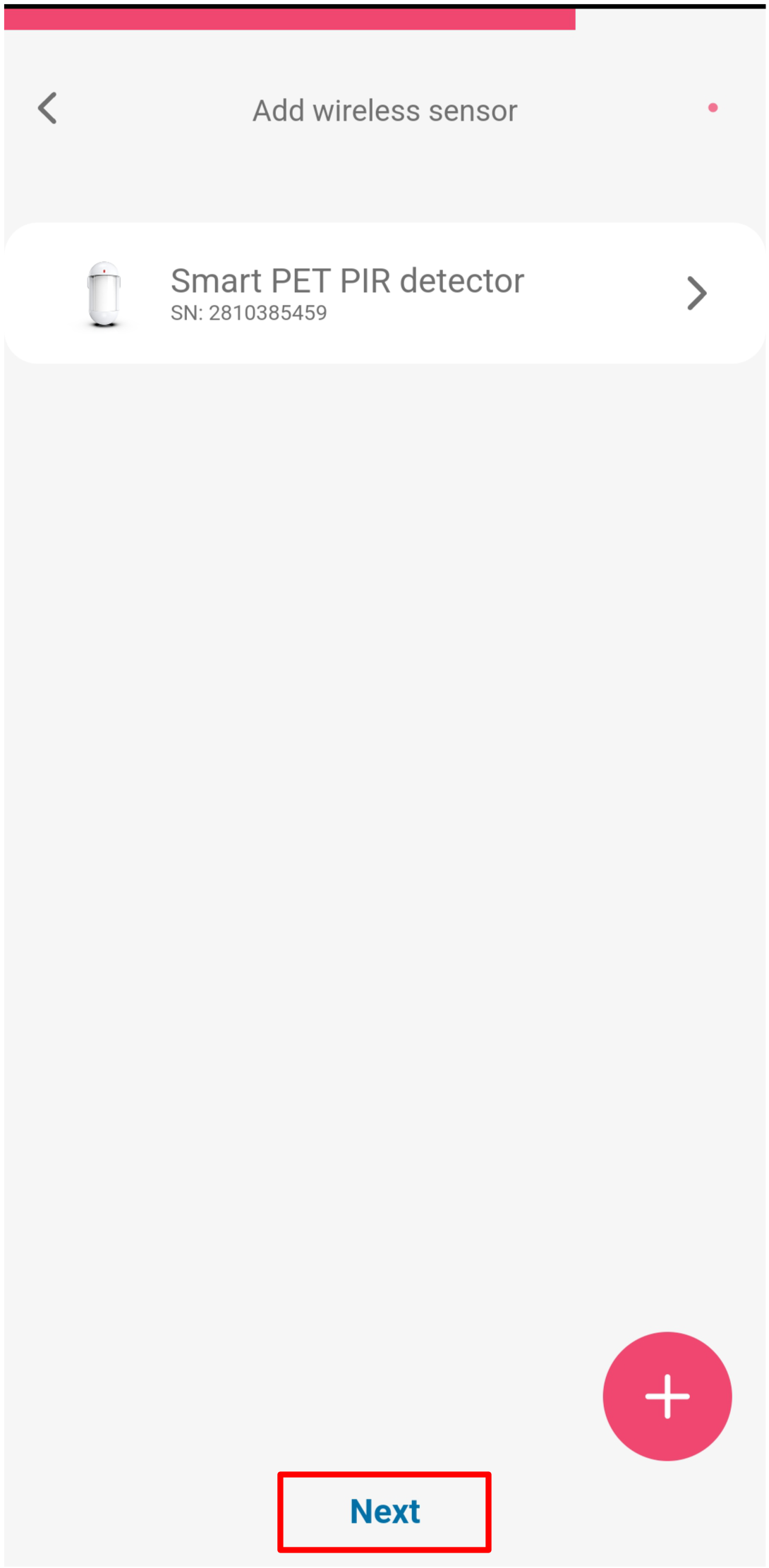
To add another sensor, tap + and repeat steps 5–10. When all sensors are paired, tap Next.
-
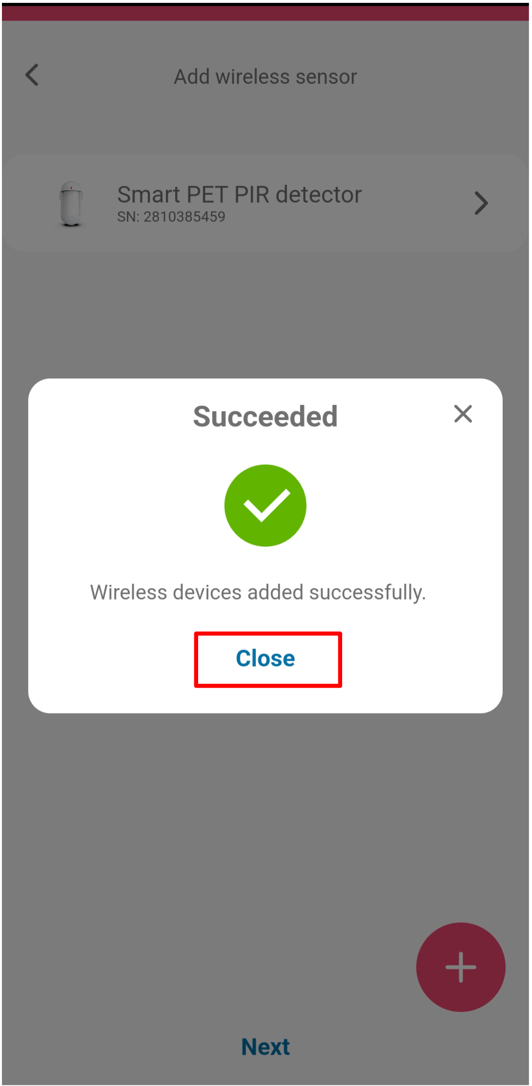
A success dialog confirms the pairing. Tap Close.
Verify zone status:
-
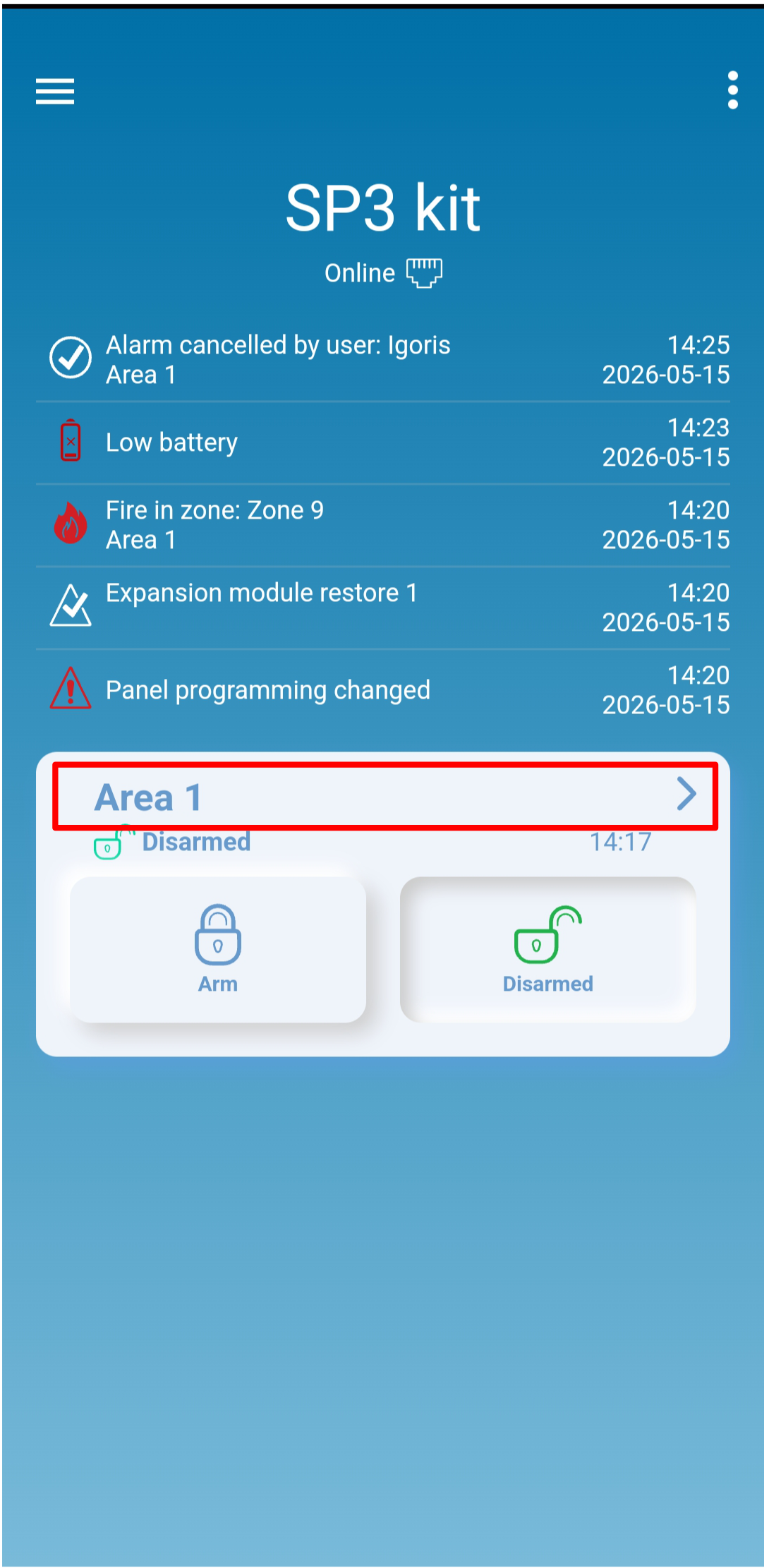
From the system home screen, tap the Area 1 tile.
-
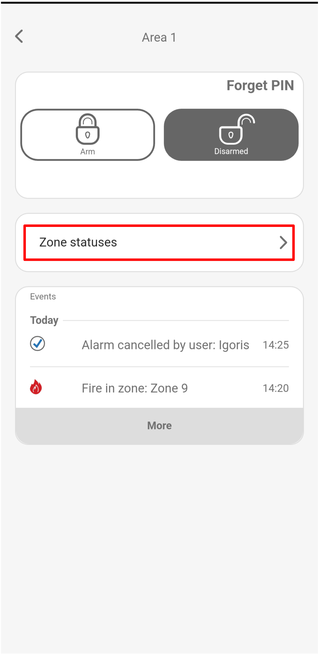
Tap Zone statuses.
-
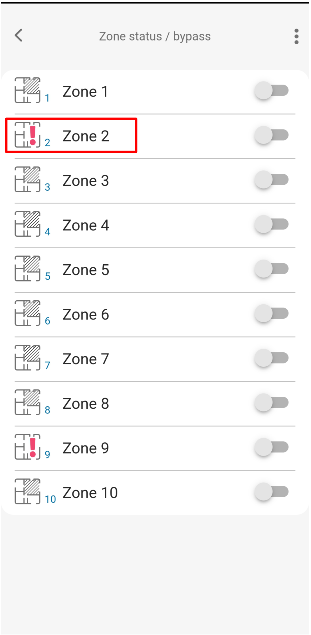
The Zone status / bypass screen lists all zones. A red alert icon means the sensor is currently open or triggered. Bypass toggles let you temporarily disable individual zones.
Open web.protegus.app in a desktop browser. The SP3 system must already be added to your account.
-
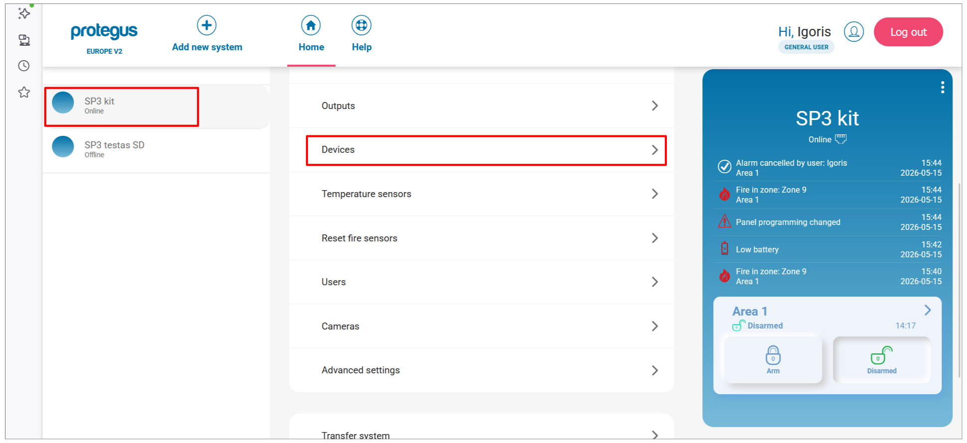
Select the SP3 system from the left panel, then click Devices in the system menu.
-
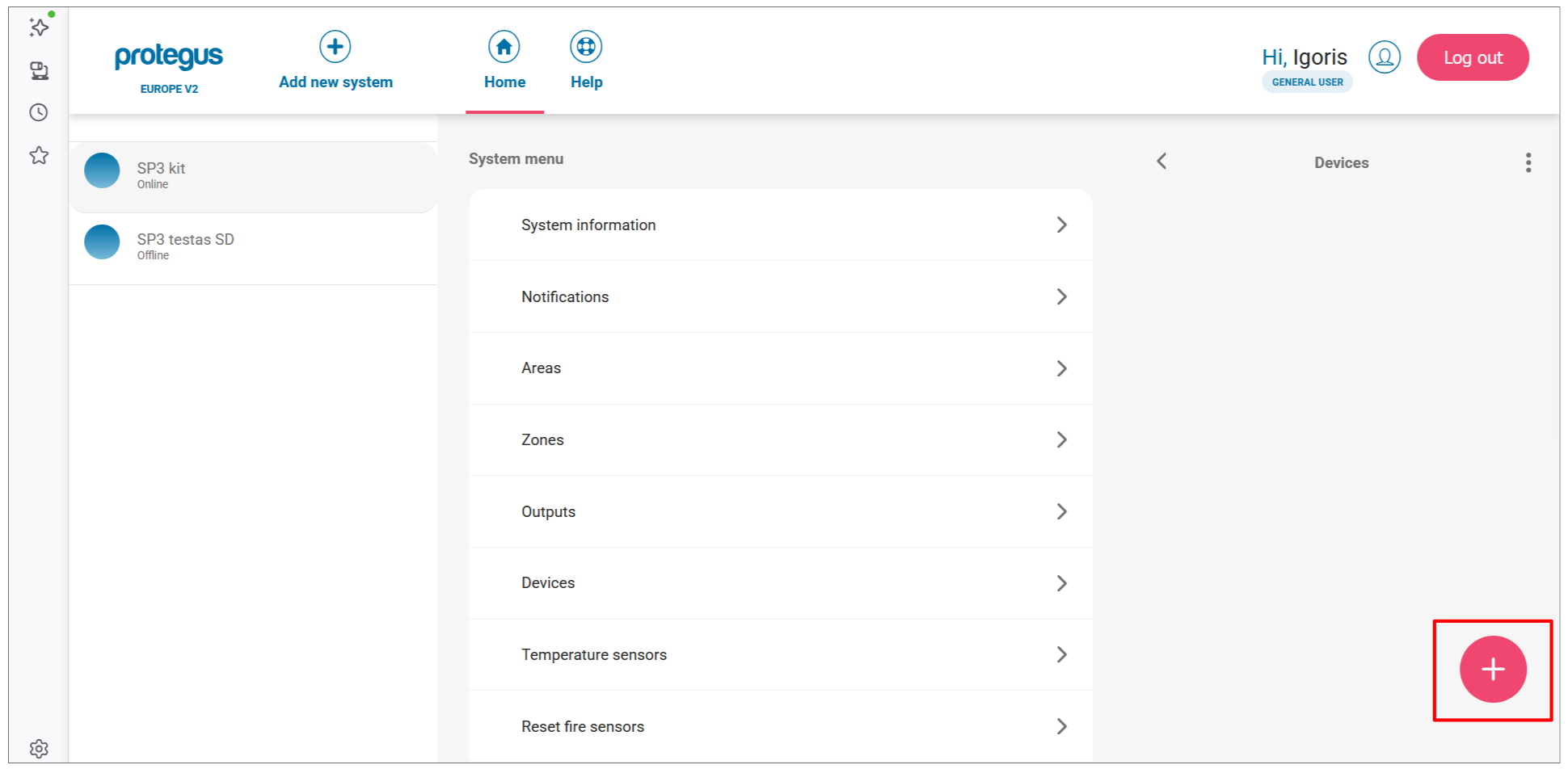
Click the + button to add a new wireless sensor.
-
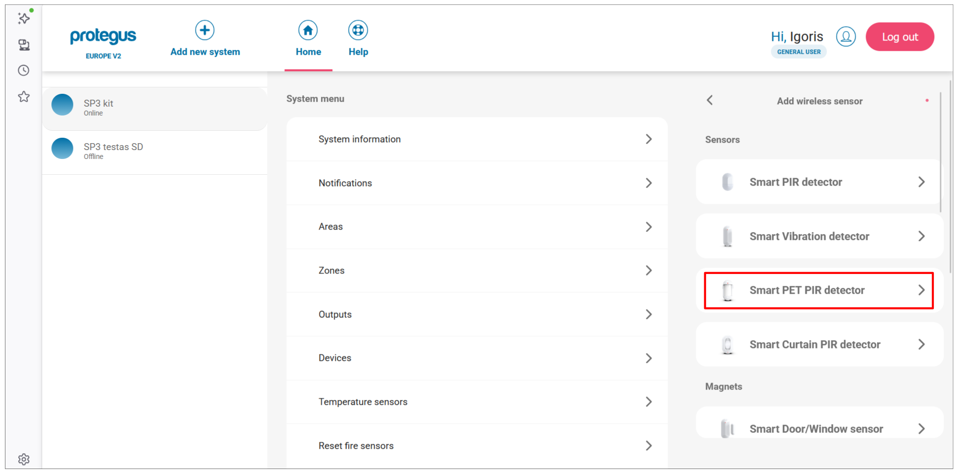
The Add wireless sensor panel opens with all supported sensor types. Click the sensor type you want to pair (e.g. Smart PET PIR detector).
-
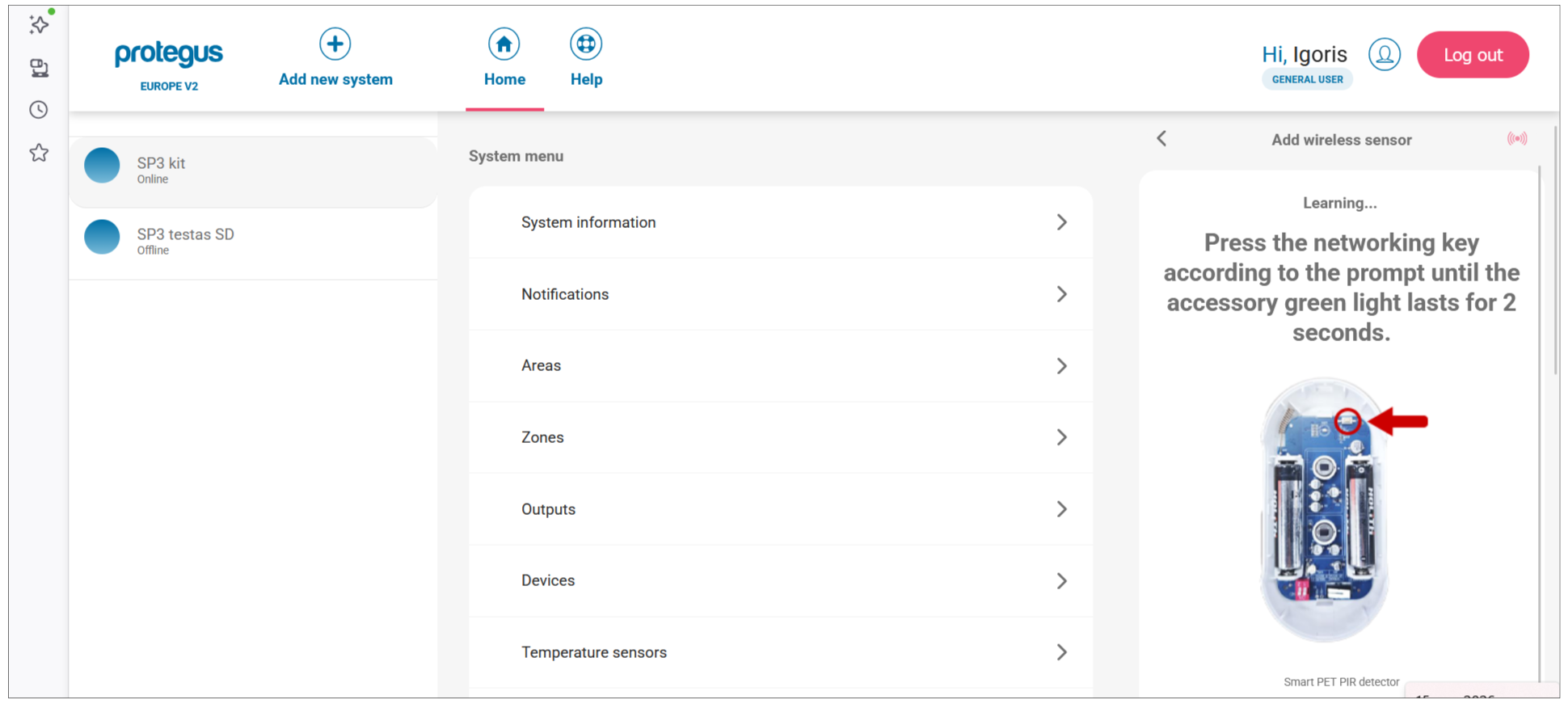
The app switches to Learning mode and shows the sensor with a diagram indicating the learn button location.
Press and hold the learn button until the green indicator stays lit for 2 seconds (approximately 4–5 seconds).
-
When the panel detects the sensor, a confirmation appears with its serial number. Click OK.
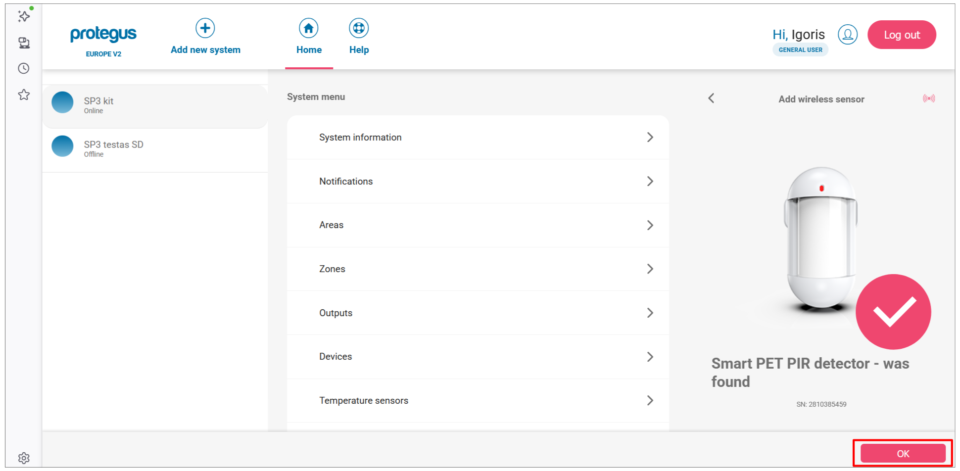
-
The sensor appears in the list with a NEW badge. To add another sensor, click + and repeat steps 3–5. When all sensors are paired, click Next.
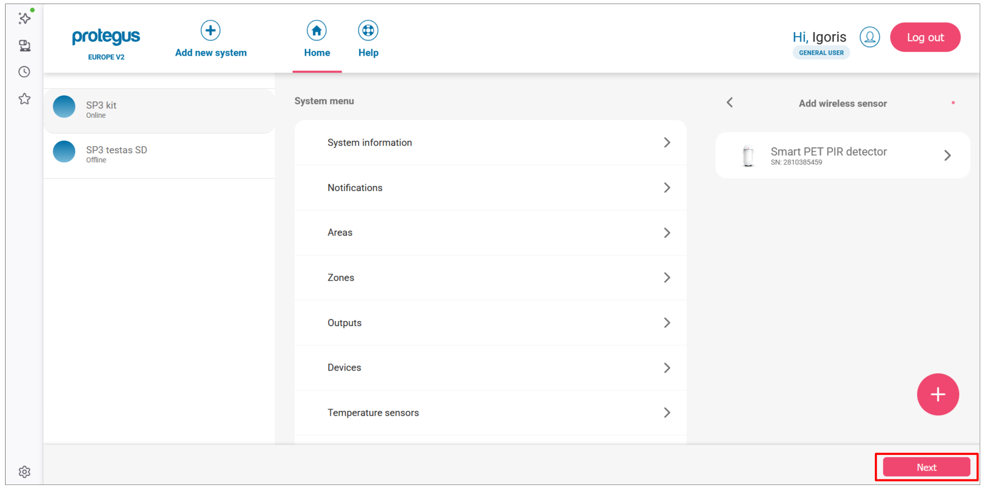
-
A success dialog confirms the pairing. Click Close.
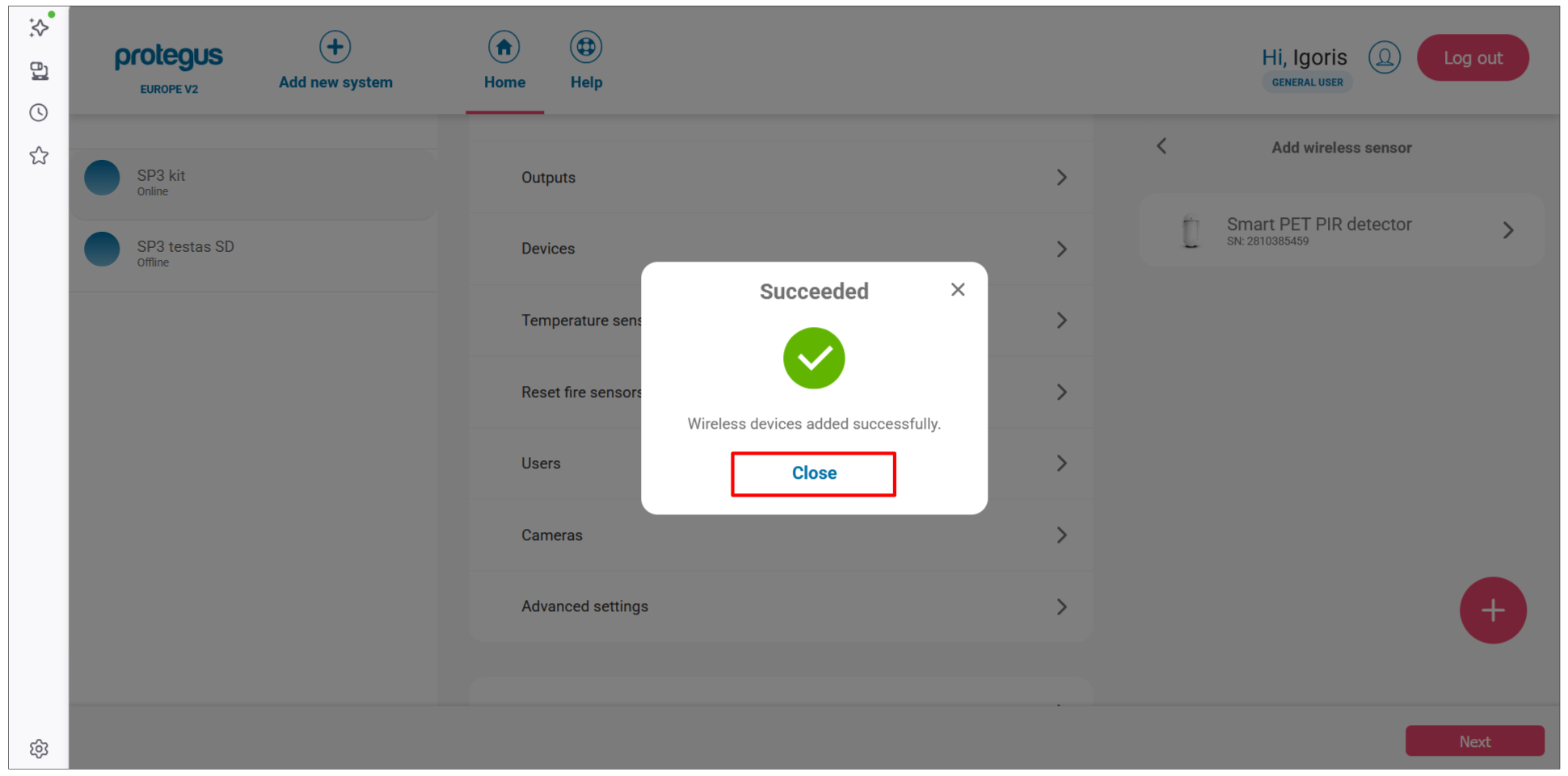
Configure zone settings:
-
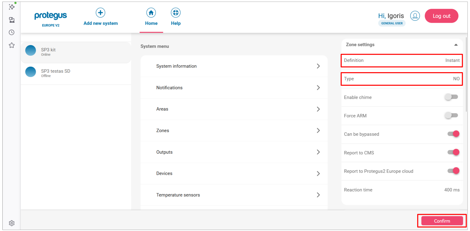
In the Devices list, click a paired sensor to open its settings. Click Zone settings to expand the section.
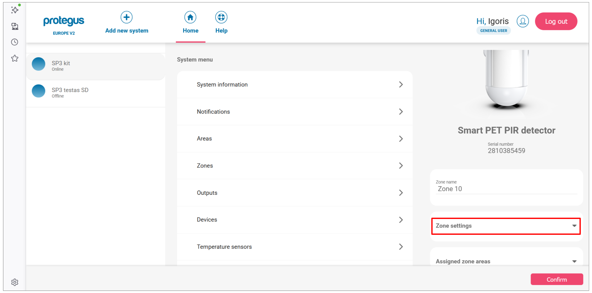
-
Set the Definition (e.g. Instant) and Type (e.g. NO) for the zone.
Verify zone status:
-
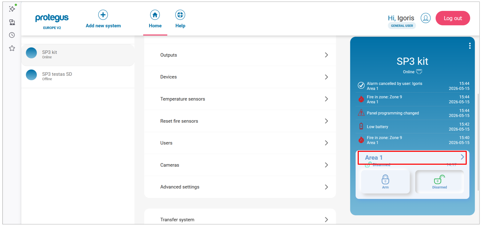
From the home screen, click the Area 1 tile.
-
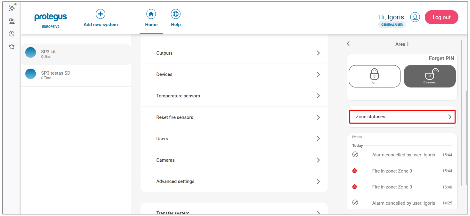
Click Zone statuses.
-
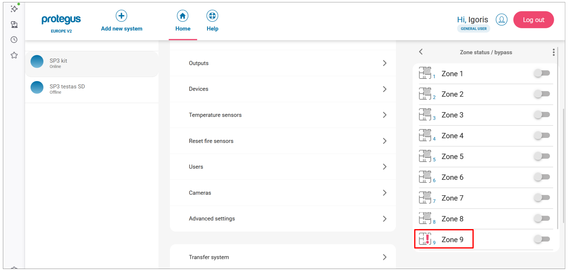
The Zone status / bypass panel lists all zones. A red alert icon on a zone means the sensor is currently open or triggered. Bypass toggles let you temporarily disable individual zones.
Two sub-methods: remote (over network) or local (USB, no network needed).
Remote pairing
Requirements: activated SIM with PIN disabled, mobile internet on SIM, Protegus cloud enabled, SP3 powered on (PWR LED green blinking), SP3 online (NET LED green solid + yellow blinking).
Warning
Never enroll or unenroll sensors while the panel is in learning mode for a different operation. Before pairing, unenroll each sensor first: hold learn button 5 s → three green flashes. If a sensor is accidentally unpaired it stops working until re-paired.
-
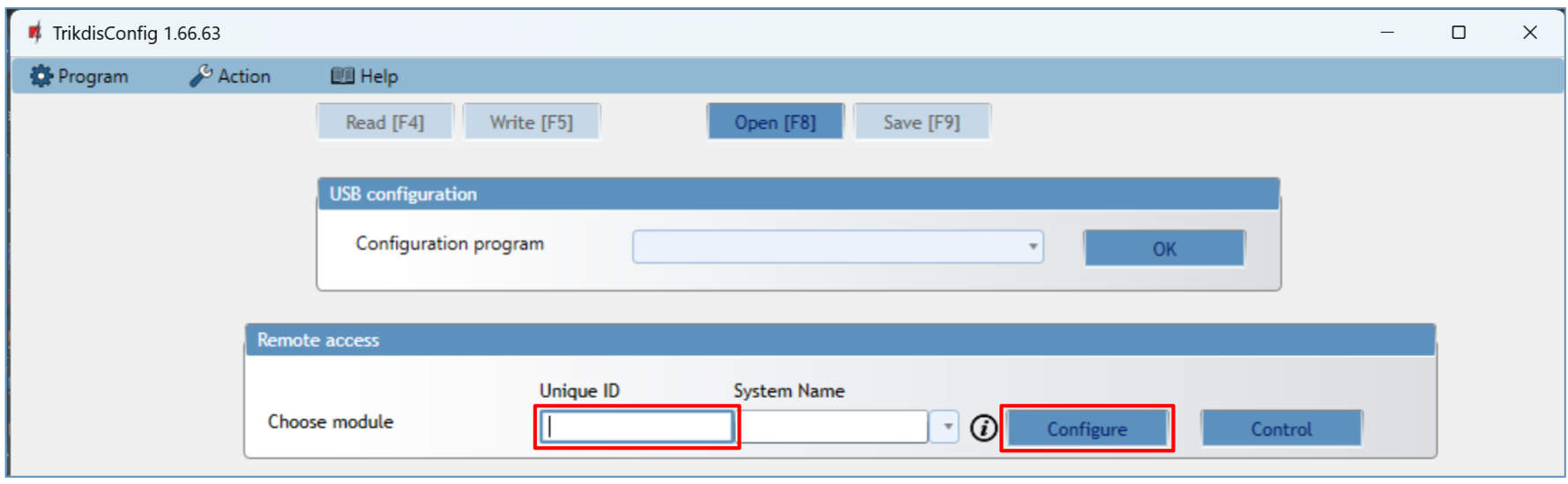
Open TrikdisConfig. In the Remote access section, enter the panel's Unique ID (printed on the device label), then click Configure.
-
Click Read [F4]. Enter admin or installer code if prompted.
-
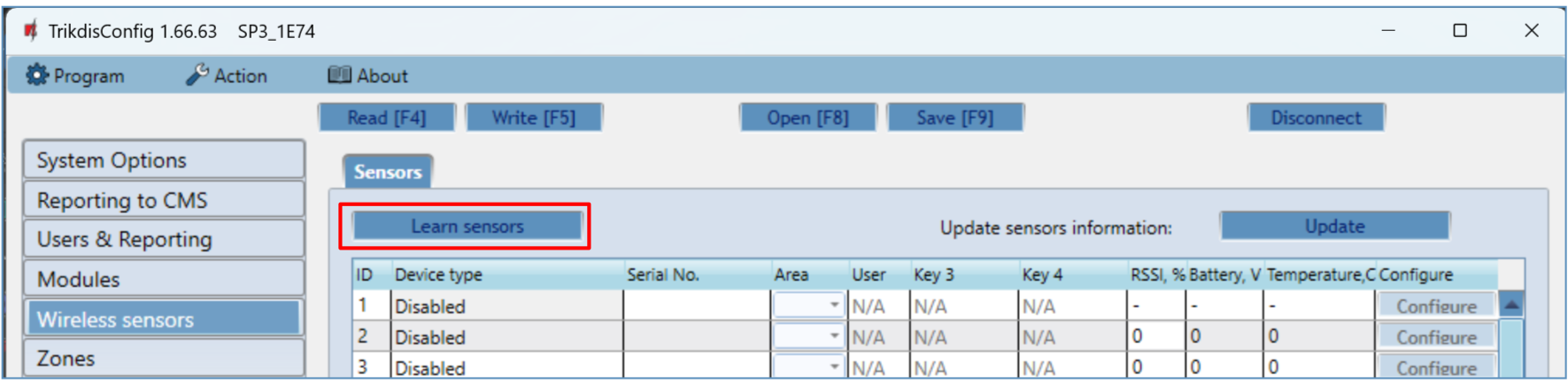
Go to Wireless sensors and click Learn sensors.
-
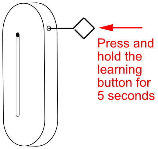
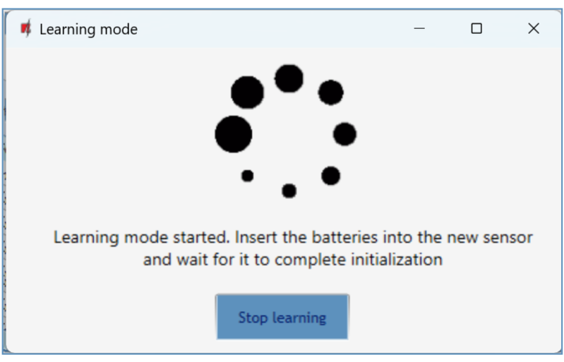
The Learning mode dialog opens. For each sensor, press and hold the learn button for 5 seconds until it flashes green four times.
-
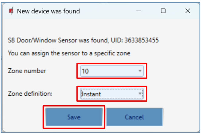
When a sensor is detected, the New device was found dialog opens. Set the Zone number and Zone definition (e.g. Instant), then click Save.
-
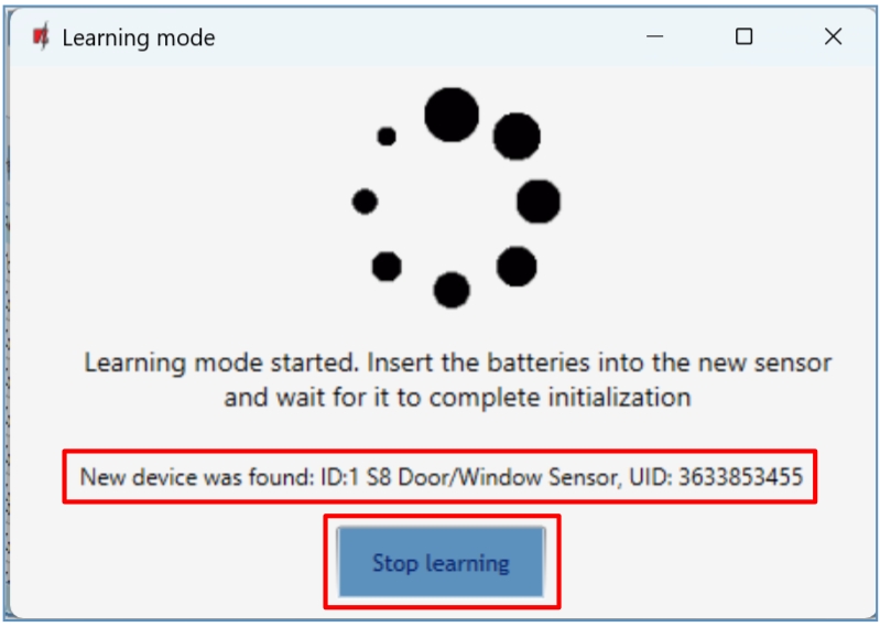
The Learning mode status line confirms the device was registered. Repeat steps 4–5 for each additional sensor.
-
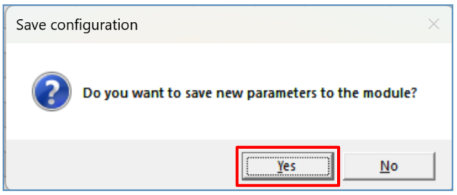
Click Stop learning. When prompted to save the new parameters, click Yes.
-
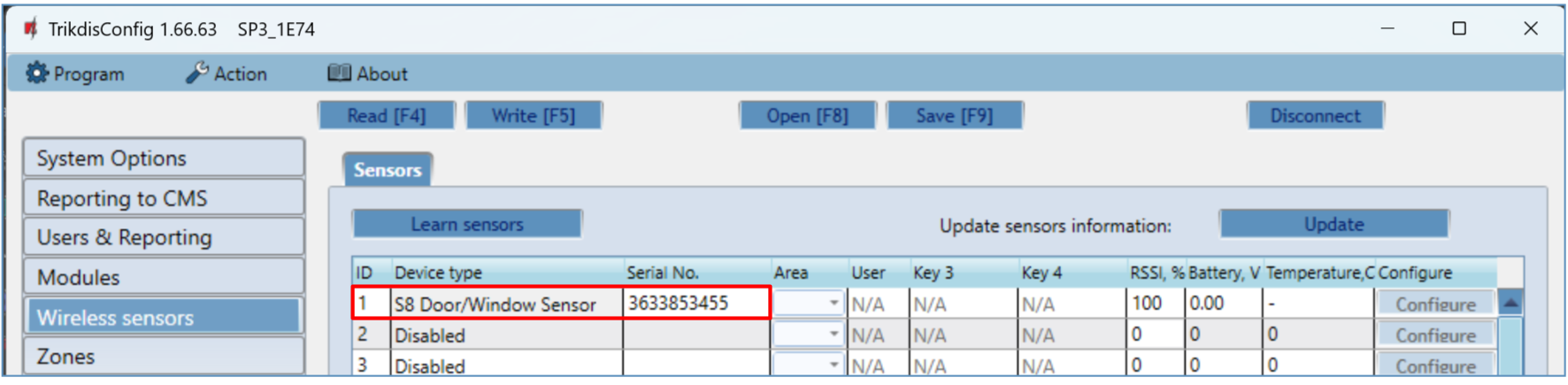
Click Read [F4]. The Wireless sensors tab now lists all registered sensors with their serial numbers.
-
Open the Zones tab. Confirm zone and area assignments. Set Type to
EOL-Tto enable tamper monitoring. Click Write [F5].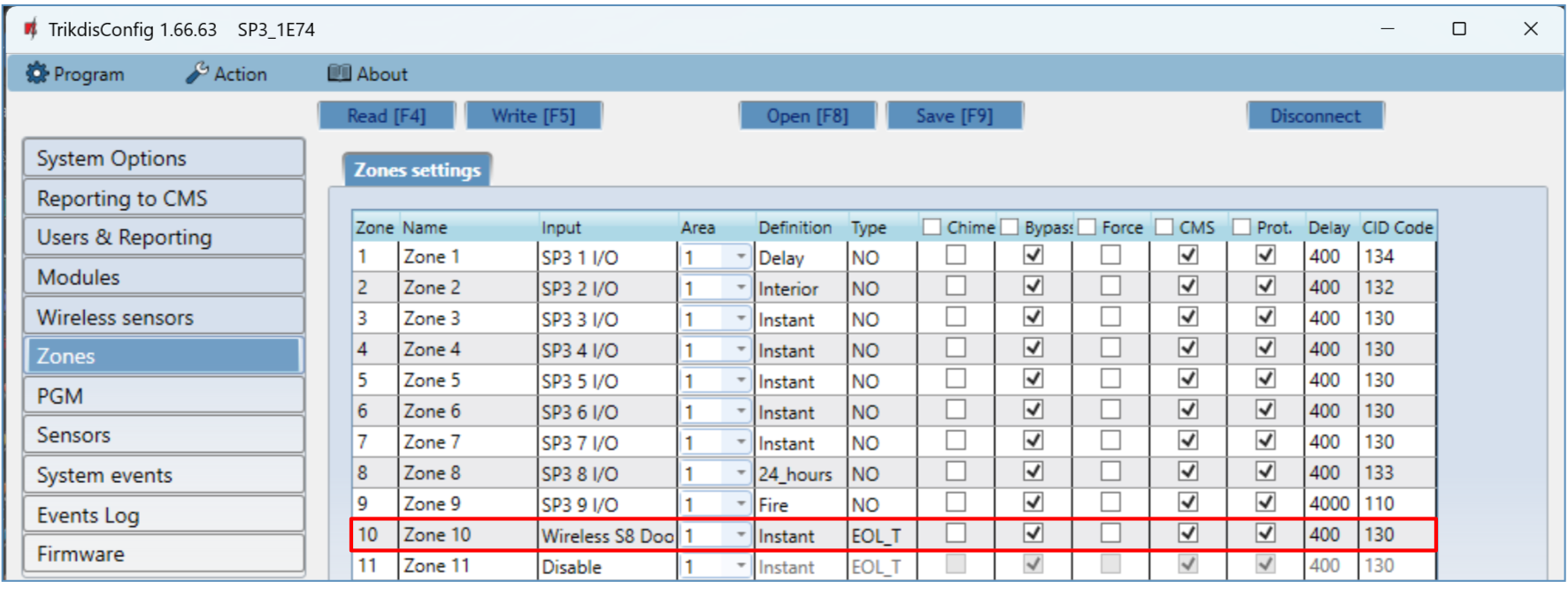
Local pairing (no network)
The RF-S8 transceiver has a LEARN button on its circuit board — use it to enter and exit learning mode without a PC connection.
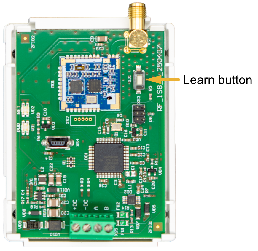
- Confirm the RF-S8 is registered with the SP3 (visible in Modules list after firmware setup).
- Power on the SP3.
- Remove the RF-S8 cover.
- Hold the RF-S8 LEARN button until the NETWORK LED flashes green/red. Release.
- Pair each sensor: hold learn button 5 s → four green flashes. NETWORK LED turns solid green briefly after each success.
- When done, hold the RF-S8 LEARN button until NETWORK LED stops flashing. Release — transceiver exits learning mode.
- Connect USB Mini-B to SP3. Open TrikdisConfig → Read [F4].
- Confirm serial numbers in Wireless sensors tab.
- Assign zones and areas in the Zones tab → Write [F5].
Remove a wireless sensor
- Connect to SP3 (USB or remote) → Read [F4].
- In Wireless sensors, set the sensor's Device type to
Disabled. - Click Write [F5].
1. LED reference — RF-S8 transceiver
| LED | State | Meaning |
|---|---|---|
| NETWORK | Flashing green/red | Learning mode active |
| NETWORK | Solid green (5 s) | Sensor successfully enrolled |
| POWER | Off | No supply voltage |
| POWER | Green blinking | Normal operation |
| POWER | Yellow blinking | Supply voltage low (≤ 11.5 V) |
| POWER | Yellow solid | No RS485 communication with SP3 |