iO-8 Input/Output Expander
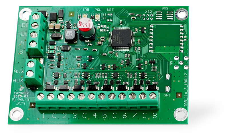
With expander iO-8 you can increase the number of inputs and outputs in a compatible TRIKDIS device.
iO-8 has 8 contacts, which can be set to either input or output mode.
Visit iO-8 page on trikdis.com for device specifications and an up-to-date list of compatible TRIKDIS devices.
Compatible with SP3, CG17, GT+, GT, G16, G16T, G17F, E16, E16T, GATOR Cellular and GATOR WiFi.
Follow these steps to set up iO-8:
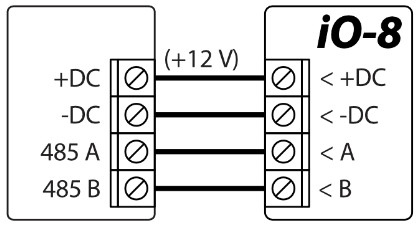
- Wire iO-8 to a compatible TRIKDIS device as shown:
- Wire inputs as shown:
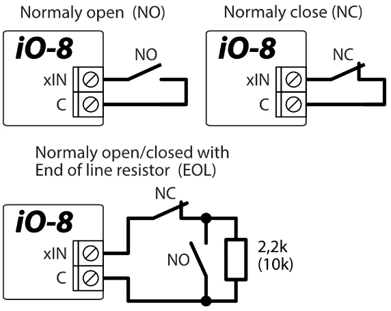
The input wiring diagrams and resistor values are determined by the main unit to which the iO-8 module is connected.
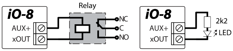
- Wire outputs as shown:
-
Connect a USB cable to the main TRIKDIS device and open TrikdisConfig software. Press Read [F4].
-
Go to Modules window, and click on a free row in the "RS485 modules" pane. Select "iO-8 expander" in the drop-down list as shown:
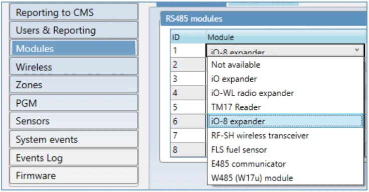
-
Enter iO-8 Serial No. (numbers only) in the cell to the right. You will find this number on the sticker on iO-8.
-
In the Input and PGM Output drop-down menu selection (Zones and PGM window), you will now see the iO-8 inputs and outputs, which you can enable:
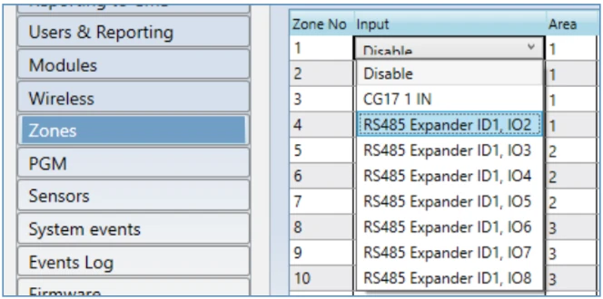
The setup may differ depending on the main TRIKDIS device. Configure settings for zones and PGM outputs according to the manual of the main device.
-
Once finished, press Write [F5] and disconnect USB cable.
-
Trigger the inputs and switch outputs to test the installation.