RT2 Telephone Line Receiving Module
Receiving module is used as component of multi-channel receiver RM10 and RD10 and is designed for receiving of data being sent via telephonic lines.
Data exchange is being carried out via following protocols:
- Contact ID
- Ademco Express 4+2
- SIA FSK
- Pulse 3/1, 4/1, 4/2 protocols
1. Description of Operation Principles and Key Features
Receiving module RT2 is a device, providing receiving of reports from telephonic communicator of security control panel. Information is being processed (provided communication according to selected protocols) and transferred to concentrator of multi-channel receiver.
Microcontroller performs processing of signals. It recognizes data being transferred and generates messages of set structure, which via serial port are being transferred to concentrator of multi-channel receiver either RD10 or RM10.
Receiving module RT2 has no any programming filters.
2. Specifications
-
Receiving module RT2 provides data reception from security control panel to centralized monitoring station via telephonic lines. Type of telephone line is tonal or pulse.
-
Receiving module RT2 operates with lines with operating voltage up to 65V and maintains alternating call voltage up to 250V.
-
Receiving module RT2 receives messages being transferred via telephone lines by using following protocols:
- Contact ID according to standard SIA DC-05-1999.09
- Ademco Express 4+2
- SIA Format according to standard SIA DC-03-1990.01 1st. and partially 2nd. levels
- Pulse 3/1, 4/1, 4/2 protocols, operating at the speed of 10...40 bauds and by using 1400 Hz or 2300 Hz HSK and kissoff signals
-
Receiving module RT2 should be mounted either into multi-channel receiver RM10 or receiver RD10 and is powered with its 12.6 V voltage. Permissible voltage variation is from 11 to 15 V. Current not exceeding 150 mA.
-
Receiving module operates at the temperature range from -10°C to +55°C under relative humidity up to 90% near +20°C.
-
Overall dimensions of the module do not exceed 190 x 130 x 30 mm.
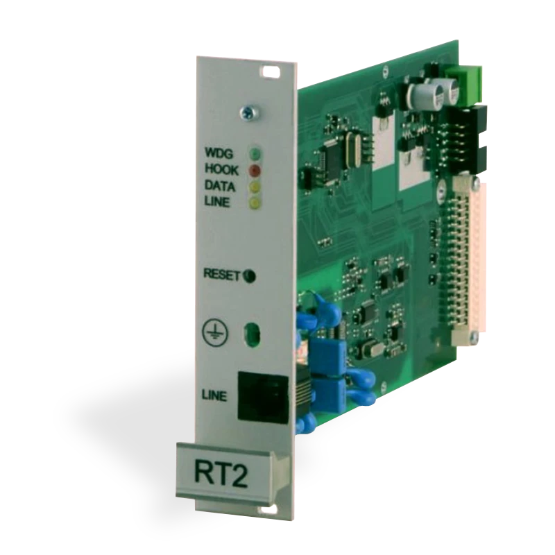
3. LED Indicators
Receiving module RT2 has four LEDs on the front panel:
| LED | Color | Indication |
|---|---|---|
| 1 | Yellow | Line control — lights constantly under properly functioning telephone line |
| 2 | Red | Handset lift — lights constantly if handset is lifted |
| 3 | Yellow | Data reception — flashes during data reception from peripheral device |
| 4 | Green | Power supply / operation — flashes in short periods under power supply voltage on and under operation of processor |
4. Connectors
| No. | Connector |
|---|---|
| 5 | RESET button of the device |
| 6 | Connector for peripheral device |
| 7 | Power supply connector |
| 8 | Programming connector |
| 9 | Connector for concentrator |
5. Preparation for Operating
Receiving module RT2 should be delivered to the user regularized to receive report from communicator of security control panel:
- first, via SIA Protocol format
- second, via Contact ID or Ademco Express formats
- third, pulse protocols 3/1, 4/1, 4/2, which use 2300 Hz HSK signals
- fourth, pulse protocols 3/1, 4/1, 4/2, which use 1400 Hz HSK signals
Exploitation parameters of the module are available in the table below.
Preparation for operating steps:
- Unpack the module.
- Specify and if necessary set necessary exploitation parameters of the module.
- Unscrew decorative lid from the rear panel of the multi-channel receiver and install the reception module.
- Press RESET button.
- Connect peripheral device.
The receiving module generates service messages, indicated in Annex A.
Received messages are displayed on the monitor of multi-channel receiver and transferred to the centralized monitoring program.
6. Exploitation Parameters
Table 1. Exploitation parameters of the receiving module RT2
| Title | Permissible range | Set value |
|---|---|---|
| Number of calls while handset of the module will be lifted | 1 – 8 | 2 |
| Telephonic line control on/off | enable / disable | enable |
| Time from handset lift till start of HSK signal | 500 ms – 4000 ms | 2000 |
| Duration Kissoff (and confirmation) signals | 500 ms – 8000 ms | 900 |
| Time period between HSK signals | 1 s – 16 s | 4 |
| Permissible duration of message reception | 2 s – 16 s | 2 |
| SIA HSK duration | 500 ms – 2000 ms | 900 |
| Common time limit for a single communication session | 15 s – 255 s | 60 s |
| Time limit for reception of SIA blocks | 1 – 32 s | 8 s |
| HSK order — SIA FSK HSK | SIA FSK HSK | SIA FSK HSK |
| HSK order — Dual tone HSK (1400+2300 Hz) | Dual tone HSK (1400+2300 Hz) | Dual tone HSK (1400+2300 Hz) |
| HSK order — Pulse 3/1, 4/1, 4/2 with 2300 Hz | 3/1, 4/1, 4/2 | 2300 Hz |
| HSK order — Pulse 3/1, 4/1, 4/2 with 1400 Hz | 3/1, 4/1, 4/2 | 1400 Hz |
7. Indication of Received Message
View of the service message, generated by the module RT2 and displayed on the LCD monitor of multi-channel receiver RD10 (or RM10):
40-5 MODULE RESET
Where:
40— Type of reception module (RT2 type 40)5— Channel (line) numberMODULE RESET— service message
View of the event message:
04-1 12:38:15 7678 E130 01 001
Where:
40— Type of reception module (RT2 type 40)1— Channel (line) number12:38:15— Reception time7678— Account numberE130— Event code01— Subgroup number001— Event place or number of user's code
8. Setting of Exploitation Parameters
Exploitation parameters of the module RT2 should be set by using programming device SPROG-1 and application of exploitation parameters setting GProg.
By using programming cable couple programming port of the RT2 module with the programming device SPROG-1 and activate application GProg.
- Go to Setup → Serial port; window of serial port will be displayed. Set number of communication port, the device is connected to.
- Select programmable device Devices → RI4010 → RT2 and read its exploitation parameters by pressing button [Read].
- When the module operates as components of multi-channel receiver, set Surgard protocol.
- Under necessity, parameters may be changed. Enter changed parameters by pressing button [Write].
9. Annex A — Service Messages
Service messages of telephonic communication reception module RT2:
| Message | Code | Description |
|---|---|---|
| COM TROUBLE | 05 | Communication failure between the device and concentrator |
| COM RESTORE | 06 | Communication with the concentrator restored |
| TEL LINE ERROR | 20 | Telephone line failure or disconnection |
| TEL LINE OK | 30 | Telephone line restored |
| MODULE DISCONNECT | C0 | Device disconnected |
| MODULE CONNECT | C1 | Device connected |
| RT2 RESET | D0 | RESET button of RT2 module is pressed |