RTH2 Telephone Line Receiver
1. About Telephone Line Receiver
Telephone line Receiver RTH2 receives event reports from security control panel's telephone communicator. Received events are processed and transferred to the monitoring software.
Note
We configure the receiver with preset settings on client's request.
2. Technical Parameters
| Name | Description |
|---|---|
| Communication channel | Telephone lines — tonal or pulse |
| Receiving formats | Contact ID, SIA, Ademco Express 4+2 and others |
| Primary power supply | 100 – 240 V (50 / 60 Hz) AC network |
| RS232 data output ports | 1 x DB9 |
| Operating temperature | From 0°C to +55°C |
| Dimensions | 225 x 235 x 115 mm |
| Weight | 1.21 kg, with cables |
2.1 Report Receiving Technology
| Name | Description |
|---|---|
| 1. SIA Protocol format | Standard SIA DC-03-1990.01 |
| 2. Contact ID | Standard SIA DC-05-1999.09 |
| 3. Ademco Express 4+2 formats | Standard SIA DC-05-1999.09, 4+2 format with checksum — 4 digit account code, 2 digit event code, 1 digit checksum |
| 4. Pulse protocols 3/1, 4/1, 4/2, which use 2300 Hz HSK signals | Operating at the speed of 10...40 bauds and by using 2300 Hz HSK and kissoff signals |
| 5. Pulse protocols 3/1, 4/1, 4/2, which use 1400 Hz HSK signals | Operating at the speed of 10...40 bauds and by using 1400 Hz HSK and kissoff signals |
3. Receiver Assembly
| Item | Quantity |
|---|---|
| Receiver | 1 pc. |
| 1.5 m power supply cable | 1 pc. |
| 1.8 m RS232 Null Modem cable | 1 pc. |
Note
SPROG-1 or UP2 cables for receiver programming are not included.
4. Power Supply
The receiver is powered with the alternating current (AC) source. To ensure an uninterrupted operation the receiver should be connected to a 12 V, 7Ah battery, providing backup power supply for 12 hours.
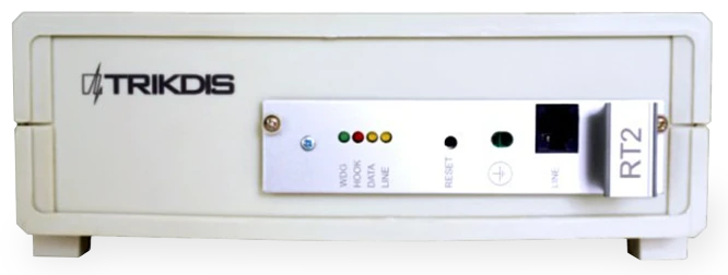
5. Receiver Structure
5.1 Front view
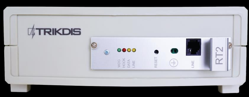
| No. | Element |
|---|---|
| 1 | Light indication (WDG, HOOK, DATA, LINE LEDs) |
| 2 | RESET button of the device |
| 3 | Earth connection |
| 4 | Connector — telephone line input |
5.2 Rear view
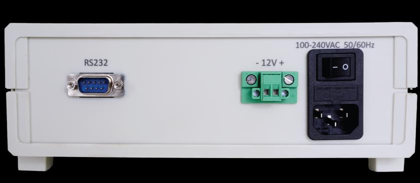
| No. | Element |
|---|---|
| 5 | RS232 data output port |
| 6 | Backup battery connection (-12V+) |
| 7 | AC cable connector (100-240VAC 50/60Hz) and turn on/off button |
5.3 Light Indication
| LED Indicator | Operation | Value |
|---|---|---|
| "LINE" yellow — Telephone line operation | Off | Telephone line not connected or not available |
| "HOOK" red — Handset lift | Lights up | Handset is lifted |
| "DATA" yellow — Data reception | Flashing yellow | During data reception from a peripheral device |
| "WDG" green — Power supply status | Flashes in short periods | Power supply voltage during standby and operation |
6. System Installation
6.1 Equipment Installation Steps
Note
1) SPROG-1 or UP2 cables for receiver programming are not included with the receiver. 2) To set the parameters you need to install GProg2 software. To download GProg2 installation file go to www.trikdis.com
- If received device does not have preset exploitation parameters, please set them as described in Setting of Exploitation Parameters below.
- Connect receiver to computer using RS232 cable to forward events to the monitoring software.
- Set up your monitoring software to display receiver messages. Please follow instructions in your monitoring software documentation.
- Connect AC power supply cable.
- Turn on the receiver. Receiver is working properly when LED named "WDG" is flashing.
- Press RESET button.
- Check if your monitoring software are displaying messages from RTH2 receiver.
If nothing was received: check LED "Line" — it should be yellow. If not, recheck connections. In case that problem still occurs, please make sure that exploitation parameters are set correctly or contact technical support. How to check and change parameters please refer to Setting RTH2 Exploitation Parameters with GProg2 below.
Note
The integrated receiving module generates service messages, indicated in Annex A.
7. Setting of Exploitation Parameters
7.1 Exploitation Parameters of the Receiver
| Title | Permissible range | Set value |
|---|---|---|
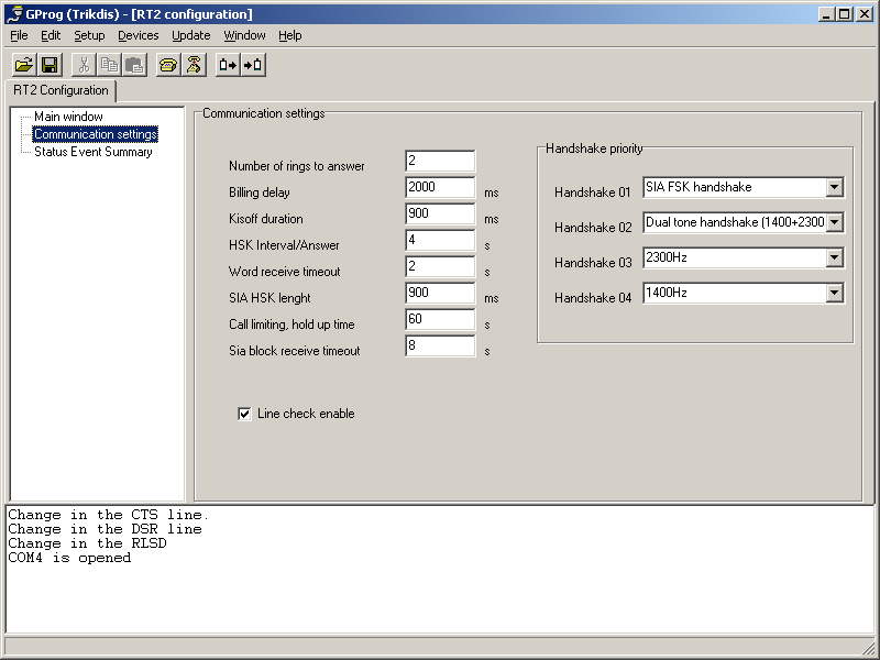
| Number of rings until handset of the module will be lifted | 1 – 8 | 2 |
| Telephonic line control on/off | enable / disable | enable |
| Time from handset lift till start of HSK signal | 500 ms – 4000 ms | 2000 |
| Duration Kissoff (and confirmation) signals | 500 ms – 8000 ms | 900 |
| Time period between HSK signals | 1 s – 16 s | 4 |
| Permissible duration of message reception | 2 s – 16 s | 2 |
| SIA HSK duration | 500 ms – 2000 ms | 900 |
| Common time limit for a single communication session | 15 s – 255 s | 60 s |
| Output protocol | Surgard or Radionics D6600 | Surgard |
| Time limit for reception of SIA blocks | 1 – 32 s | 8 s |
| HSK order (priority of reception protocols) — SIA FSK HSK | SIA FSK HSK | SIA FSK HSK |
| HSK order — Dual tone HSK (1400+2300 Hz) | Dual tone HSK (1400+2300 Hz) | Dual tone HSK (1400+2300 Hz) |
| HSK order — Pulse 3/1, 4/1, 4/2 with 2300 Hz | 3/1, 4/1, 4/2 | 2300 Hz |
| HSK order — Pulse 3/1, 4/1, 4/2 with 1400 Hz | 3/1, 4/1, 4/2 | 1400 Hz |
7.2 Setting RTH2 Exploitation Parameters with GProg2
The receiver parameters can be set via SPROG-1 or UP2 programmer using GProg2 software. Also you may need to install USB driver. The GProg2 and USB drivers are available on our website www.trikdis.lt.
Note
The software GProg2 should be installed into PC, operating OS MS Windows 2000/XP/Vista/Win 7.
7.2.1 Connecting to Computer
- Open the RTH2 housing and take out the module (do not forget to disconnect backup battery).
- Connect the module to power supply.
- Connect the module to a computer with SPROG-1 or UP2 programmer.
7.2.2 Installing USB Driver
USB drivers must be installed on the computer. When the module connects to a computer for the first time, MS Windows OS should open the window Found New Hardware Wizard for installing USB drivers.
- Download the USB driver file *.inf for MS Windows OS from the website www.trikdis.lt.
- In the wizard window select the function [Yes, this time only] and press the button [Next].
- When the window Please choose your search and installation options opens, press the button [Browse] and select the place where the file *.inf was saved.
- Follow the remaining wizard instructions to finish the USB driver installation.
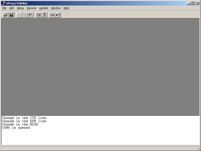
7.2.3 Starting GProg2
- Start program by clicking the GProg2 icon
 , then in the Settings window specify the serial port (e.g.: COM3).
 - In menu bar choose command [Devices] and select RT2.
- Press the
 icon in toolbar to connect receiver.
 - To read the operational parameters stored in the internal memory of device, press the
 button.
 - When data download has finished a window Configuration is received will appear.
7.2.4 Toolbar Icons Description
| Icon | Function |
|---|---|
| Open saved file with extension ".tcfg" | |
| Save established parameters file with extension ".tcfg" | |
| Connect to serial port | |
| Disconnect from serial port | |
| Read parameters of the device | |
| Write the new parameters into device memory | |
| Print established parameters report |
7.2.5 Setting Parameters
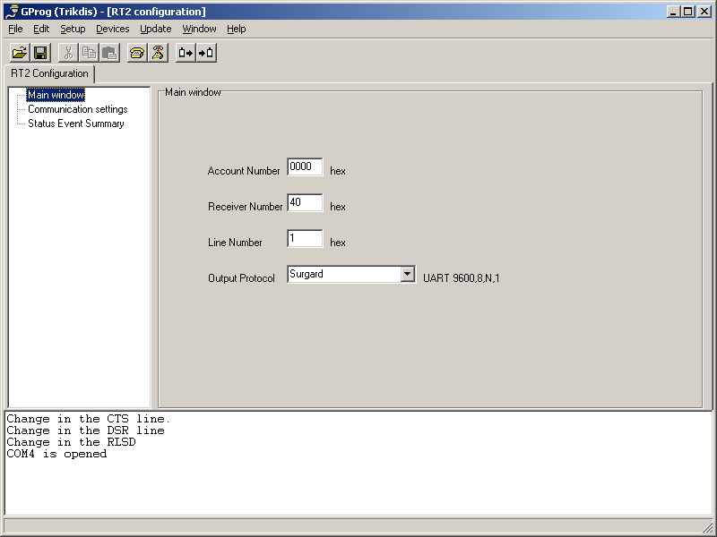
- In branch Main window set Surgard protocol.
- If necessary, you can change parameters in branch Communication settings — the recommended values are shown in Exploitation Parameters of the Receiver above.
- To save parameters go to [File/Write device] in menu bar or press the
 icon.
icon. - To save set parameters in your computer, go to [File/Save as]. File name, place to save may be selected freely. It can be used later as a template to configure other modules.
8. Annex A — Service Messages
Service messages of telephonic communication receiver:
| Message | Code | Description |
|---|---|---|
| COM TROUBLE | 05 | Communication failure between the device and concentrator |
| COM RESTORE | 06 | Communication with the concentrator restored |
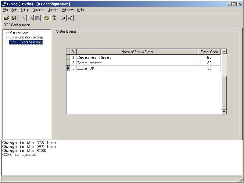
| TEL LINE ERROR | 20 | Telephone line failure or disconnection |
| TEL LINE OK | 30 | Telephone line restored |
| MODULE DISCONNECT | C0 | Device disconnected |
| MODULE CONNECT | C1 | Device connected |
| RECEIVER RESET | D0 | RESET button of receiver is pressed |